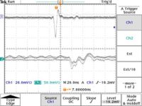
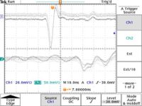
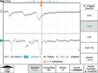
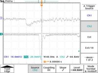
Metalica TestPulseoutput 12-21-07
12/21/07
The scope pictures show the PREamp output on Channel 2 given the input pulse shown on Channel 1 that is input directly onto the sense wire.
The CAEN N470 power supply was used to establish voltages onthe drift chambers. A SHV tee was used to allow a single HV channel from the CAEN power supply to power both chambers in parallel. The Drift chamber voltages settings were set according to the table below. The current column indicates the total current drawn from both chambers.
| HV settings | ||
| Wire | Volts | current (A) |
| Sense | 1500 | 19 |
| Field | -800 | 19 |
| Guard | 800 | 0 |
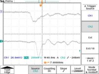
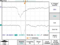
The Drift Chamber sense wire #4 (center sense wire) output is shown on channel 1 in the the scope pictures below. The POSTamp output is shown on Channel 2. There appears to be a factor of 10 gain when the drift chamber output is amplified by the peramp - postamp system which differs from the attenuation measured why injecting a pulse?
Now we looked at signals from the Drift chamber sense wire #4 in coincidence with the top scintillator paddle. The scintillator paddle output has been delayed by 100 ns.
