IAC positron beamline
Below are three possible configurations for a positron beam line at the IAC. They are listed in order of increasing complexity and difficulty and named analogously using ski trail nomenclature.
Configuration 1: "Green run"
This configuration is expected to require the minimal mount of effort (3 days) and is to be used as a "test of principle" in order to justify further investment.
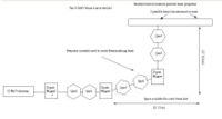
The "Green run" configuration proposes switching only two beamline elements. There are three elements between the last two Dipole magnets in the beam line. The first element is a 45 degree bending magnet. This is followed by the first quadrupole magnet of a doublet pair, then quad port for mounting targets and finally the second half of the quad doublet just before entering the last 45 degree dipole bending magnet.
The "Green run" configuration would have the first quad of the dipole doublet and the target port switch places in the beam line. The target (a Tungsten converter to produce positrons) would be placed just after the first 45 degree dipole. The quad doublet would be placed after the target and before the last 45 degree bending dipole magnet.
changes
- switch target mount assembly and dipole (3 days)
Goals
The goal this configuration will be to test positron production efficiencies and determine if the results are scalable by improving the beam line optics.
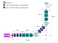
Sketched (not to scale) layout of the 25 MeV beamline:
296 cm = parrallel Distance From the end of the accelerator module (After RF cavities) to experimental cell port
280 cm = Distance From accelerator zero degree beamline to Experimental Cell Wall
56 cm = distance between flanges for the first dipole
84 cm = distance between flanges for the first quad doublet
Configuration 2: " Blue run"
This configuration is expected to require a modest amount of effort (1 week) and is to be used as improved "test of principle" in order to justify further investment.
The "Blue run" configuration would replace the quad doublet mentioned in the "Green run" configuration with the thin Quad triplets.
changes
- maching new spool pieces
- install control system for the additional quadrupole
- recondition thin quadrupoles to be more reliable and leak resistant.
Goals
The goals of this configuration would be similar to the "Green run"
Configuration 3: "Double Black Diamond"
This configuration would require a substantial amount of effort (3 weeks) and would be used as a performance test to determine the maximum positron yield from the 25 MeV linac at the IAC.
changes
- replace the first dipole with 6 quadrupoles
- replace the first 45 degree bending dipole with one that can bend the beam by 45 degree either beam left or beam right. (this will allow us keep the configuration in place and continue experiments which required the first dipole that was removed)
- replace the quad doublet between the last two dipoles with a quad triplet
- install a control system for all the new magnets
Criticisms/problems to solve
- The thin quadrupoles are difficult to maintain. Specifically new fittings for the cooling lines would need to be installed which would ease maintenance.
- There is not enough room for the target following by 6 quadrupoles. Without the target, quadrupoles 1-6 would occupy 1" more space than what exists. Moving the linac to make space is not a desirable option.
- A magnet to replace the second dipole which would bend the beam at +/- 45 degrees as well as allow the beam to pass undeflected would need to be procured
- Additional power supplies for quads 1-6 may need to be procured.
- the proposed beam line changes would require a level of effort similar to moving the Linac in order to fit additional optics elements between the last dipole and the wall
Proposed beam line
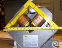
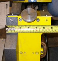
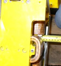
Magnet pictures
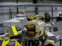
This picture shows you the current 90 degree bend into the experimental hall. Quad 1 and Quad 2 are shown and then the 2nd Dipole magnet (labeled Bending Magnet 2A a.k.a. Dipole 2) begins after Quad 1 and Quad 2. Dipole 2 is following by another Quad doublet and then a Dipole (Dipole 3) and then a final quad doublet before going through the wall into the experimental cell.
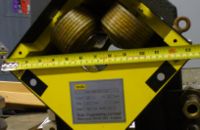
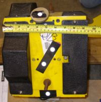
Length of Iron =
Diameter of Coils=
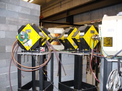
The next picture was taken upstream of the 90 degree bend and shows Dipole 1 which is usually off unless we want to bend beam right into the accelerator hall instead of going straight to Quad 1 and Quad 2.
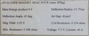
Label on side of Dipole 1
Label on side of Dipole 2
The Quad doublets in the current beam line have the following label.
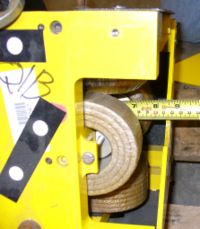
Quad doublet size:
We also have Quad triplet which take up less space than the doubles.
