Emittance
What is Emittance
In accelerator physics, Cartesian coordinate system was used to describe motion of the accelerated particles. Usually the z-axis of Cartesian coordinate system is set to be along the electron beam line as longitudinal beam direction. X-axis is set to be horizontal and perpendicular to the longitudinal direction, as one of the transverse beam direction. Y-axis is set to be vertical and perpendicular to the longitudinal direction, as another transverse beam direction.
For the convenience of representation, we use [math]z[/math] to represent our transverse coordinates, while discussing emittance. And we would like to express longitudinal beam direction with [math]s[/math]. Our transverse beam profile changes along the beam line, it makes [math]z[/math] is function of [math]s[/math], [math]z~(s)[/math]. The angle of a accelerated charge regarding the designed orbit can be defined as:
[math]z'=\frac{dz}{ds}[/math]
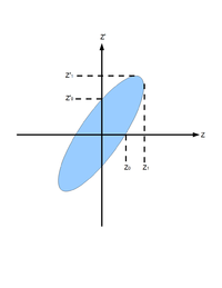
If we plot [math]z[/math] vs. [math]z'[/math], we will get an ellipse. The area of the ellipse is an invariant, which is called Courant-Snyder invariant. The transverse emittance [math]\epsilon[/math] of the beam is defined to be the area of the ellipse, which contains 90% of the particles <ref name="MConte08"> M. Conte and W. W. MacKay, “An Introduction To The Physics Of Particle Accelera
tors”, World Scientifc, Singapore, 2008, 2nd Edition, pp. 257-330. </ref>.

Fig.1 Phase space ellipse <ref name="MConte08"></ref>.
Measurement of Emittance with Quad Scanning Method
In quadrupole scan method, a quadrupole and a Yttrium Aluminum Garnet (YAG ) screen was used to measure emittance. Magnetic field strength of the quadrupole was changed in the process and corresponding beam shapes were observed on the screen.
Transfer matrix of a quadrupole magnet under thin lens approximation:
- [math]
\left( \begin{matrix} 1 & 0 \\ -k_{1}L & 1 \end{matrix} \right)=\left( \begin{matrix} 1 & 0 \\ -\frac{1}{f} & 1 \end{matrix} \right)
[/math]
Here, [math]k_{1} L[/math] is quadrupole strength, [math]L[/math] is quadrupole magnet thickness, and f is quadrupole
focal length. [math] k_{1} L \gt 0 [/math] for x-plane, and [math] k_{1} L \lt 0 [/math] for y-plane. Transfer matrix of a drift
space between quadrupole and screen:
- [math] \mathbf{S} = \left( \begin{matrix} S_{11} & S_{12} \\S_{21} & S_{22} \end{matrix} \right)=\left( \begin{matrix} 1 & l \\ 0 & 1 \end{matrix} \right)
[/math]
Here, [math]l[/math] ([math]S_{12}[/math]) is the distance from the center of the quadrupole to the screen.
Transfer matrix of the scanned region is:
[math]
\mathbf{M} =
\mathbf{SQ} =
\begin{pmatrix}
m_{11} & m_{12} \\
m_{21} & m_{22}
\end{pmatrix}=
\begin{pmatrix}
S_{11} & S_{12} \\
S_{21} & S_{22}
\end{pmatrix}
\begin{pmatrix}
1 & 0 \\
-k_1L & 1
\end{pmatrix}=
\begin{pmatrix}
S_{11} - k_1LS_{12} & S_{12} \\
S_{21} - k_1L S_{22} & S_{22}
\end{pmatrix}
[/math]
[math]\mathbf{M}[/math] is related with the beam matrix [math]\mathbf{\sigma}[/math] as:
[math]
\mathbf{ \sigma_{screen}} =
\mathbf{M \sigma_{quad} M^T} =
\begin{pmatrix}
m_{11} & m_{12} \\
m_{21} & m_{22}
\end{pmatrix}
\begin{pmatrix}
\sigma_{quad, 11} & \sigma_{quad, 12} \\
\sigma_{quad, 21} & \sigma_{quad, 22}
\end{pmatrix}
\begin{pmatrix}
m_{11} & m_{12} \\
m_{21} & m_{22}
\end{pmatrix}
[/math]
Since:
[math]
\sigma_{x}=\sqrt{\epsilon_x\beta},~\sigma_{x'}=\sqrt{\epsilon_x\gamma},~\sigma_{xx'}={-\epsilon_x\alpha}
[/math]
[math]
\mathbf{ \sigma} =
\begin{pmatrix}
\sigma_{11} & \sigma_{12} \\
\sigma_{21} & \sigma_{22}
\end{pmatrix} =
\begin{pmatrix}
\sigma_{x}^2 & \sigma_{xx'} \\
\sigma_{xx'} & \sigma_{x'}^2
\end{pmatrix}
[/math]
So, [math]\mathbf{\sigma}[/math] matrix can be written as:
[math]
\mathbf{\sigma}_{quad} =
\begin{pmatrix}
\sigma_{quad, x} & \sigma_{quad, xx'} \\
\sigma_{quad, xx'} & \sigma_{quad, x,}
\end{pmatrix} =
\epsilon_{rms, x}
\begin{pmatrix}
\beta & -\alpha \\
-\alpha & \gamma
\end{pmatrix}
[/math]
Substituting this give:
[math]
\mathbf{ \sigma_{screen}} =
\mathbf{M \sigma_{quad} M^T} =
\begin{pmatrix}
m_{11} & m_{12} \\
m_{21} & m_{22}
\end{pmatrix}
\epsilon_{rms, x}
\begin{pmatrix}
\beta & -\alpha \\
-\alpha & \gamma
\end{pmatrix}
\begin{pmatrix}
m_{11} & m_{12} \\
m_{21} & m_{22}
\end{pmatrix}
[/math]
Dropping off subscript "rms" on emittance [math]\epsilon_{rms, x}[/math]:
[math]
\sigma_{screen, 11}=\sigma_{screen, x}^2=\epsilon_x (m_{11}^2\beta - 2m_{12}m_{11}\alpha+m_{12}^2\gamma)
[/math]
Using [math]\mathbf{\sigma}[/math] matrix relations:
[math]
\sigma_{x}={\epsilon_x\beta},~\sigma_{12}={-\epsilon_x\alpha},~{\epsilon_x\gamma}=\epsilon_x \frac{1+\alpha^2}{\beta}=\frac{\epsilon_x^2+\sigma_{12}^2}{\sigma_{11}}
[/math]
Here [math]\sigma_{x}[/math] is [math]\sigma_{screen, x}[/math]. We got:
[math]
\sigma_{x}^2=m_{11}^2 \sigma_{11} + 2m_{12}m_{11} \sigma_{12} + m_{12}^2 \frac{\epsilon_x^2+\sigma_{12}^2}{\sigma_{11}}
[/math]
[math]
\sigma_{x}^2=\sigma_{11} \left(m_{11}^2 + 2m_{11}m_{12}\frac{\sigma_{12}}{\sigma_{11} }+ m_{12}^2\frac{\sigma_{12}^2}{\sigma_{11}^2}\right) + m_{12}\frac{\epsilon_x^2}{\sigma_{11}}
[/math]
[math]
\sigma_{x}^2=\sigma_{11}\left(m_{11} + m_{12}\frac{\sigma_{12}}{\sigma_{11} }\right)^2 + m_{12}\frac{\epsilon_x^2}{\sigma_{11}}
[/math]
Recall:
[math]
m_{11} = S_{11}-kLS_{12}~~~~~~m_{12}=S_{12}
[/math]
Substituting and reorganizing result in:
[math]
\sigma_{x}^2=\sigma_{11} {S_{12}^2}\left(kL - \left( \frac{S_{11}}{S_{12}} + \frac{\sigma_{12}}{\sigma_{11}} \right) \right)^2 + S_{12}^2\frac{\epsilon_x^2}{\sigma_{11}}
[/math]
Introducing constants [math]A[/math],[math]B[/math], and [math]C[/math]
[math]
A = \sigma_{11} {S_{12}^2},~~B = \frac{S_{11}}{S_{12}} + \frac{\sigma_{12}}{\sigma_{11}},~~C = S_{12}^2\frac{\epsilon_x^2}{\sigma_{11}}
[/math]
This will simplify equation to:
[math]
\sigma_{x}^2=A(kL - B)^2 + C = A(kL)^2 - 2AB(kL)+(C+AB^2)
[/math]
It is easy to see that:
[math]
\epsilon = \frac{\sqrt{AC}}{S_{12}^2}
[/math]
By changing quadrupole magnetic field strength [math]k[/math], we can change beam sizes [math]\sigma_{x,y}[/math] on the screen. We make projection to the x, y axes, then fit them with Gaussian fittings to extract rms beam sizes, then plot vs [math]\sigma_{x,y}[/math] vs [math]k_{1}L[/math]. By Fitting a parabola we can find constants
[math]A[/math],[math]B[/math], and [math]C[/math], and get emittances.
Experimental Setup
We did quadrupole scan to measure emittance of the electron beam in HRRL. In quadrupole scan method, the strength of the quadrupole magnet was changed by changing the current go through quadrupole coils. The electron beam were coming out of the gun went through quadrupole (), then beam would enter a 3-way cross. Two end of the 3-way cross was installed on the beam line. The third end of the 3-way cross was placed upward and there was a actuator installed to it. The YAG crystal was mounted in the actuator, which can put the YAG in the beam line or take it out of the beam line. A camera was placed inside the actuator to look through vacuum a window and to capture the image on the YAG crystal created by electron beam. A Faraday cup was mounted at the end of the beam line to measure the transmission of the charge.
References
<references/>
Using APA reference style.
File:Emittance.tex
Go back: Positrons
