- RC Low-pass filter
1-50 kHz filter (20 pnts)
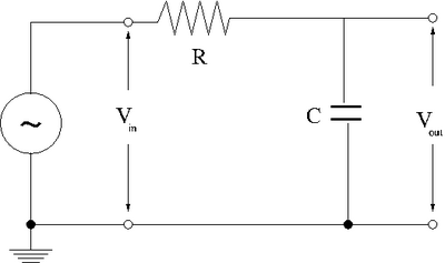
1.)Design a low-pass RC filter with a break point between 1-50 kHz. The break point is the frequency at which the filter starts to attenuate the AC signal. For a Low pass filter, AC signals with a frequency above 1-50 kHz will start to be attenuated (not passed).
- [math]\omega_{break} = \frac{1}{RC}[/math]
- [math]\Rightarrow R = \frac{1}{\omega_{break} C } = \frac{1}{25 \times 10^{3} \times 9.45 \times 10^{-9}} = 4,233 \Omega[/math]
| R |
C |
[math]\omega_B[/math] |
[math]\nu_B[/math]
|
| Ohms |
Farads |
rad/s |
Hz
|
| [math]1 \times 10^{5}[/math] |
[math]561 \times 10^{-12}[/math] |
17825 |
2837
|
| [math]96.4 \times 10^{3}[/math] |
[math]561 \times 10^{-12}[/math] |
18490 |
2943
|
| [math]10.5 [/math] |
[math]1.25 \times 10^{-6}[/math] |
76190 |
12126
|
| [math]31.3 [/math] |
[math]10.3 \times 10^{-6}[/math] |
3102 |
494
|
| [math]2.058 \times 10^5 [/math] |
[math]7.73 \times 10^{-10}[/math] |
6310 |
1004
|
2.)Now construct the circuit using a non-polar capacitor.
3.)use a sinusoidal variable frequency oscillator to provide an input voltage to your filter.
4.)Measure the input [math](V_{in})[/math] and output [math](V_{out})[/math] voltages for at least 8 different frequencies[math] (\nu)[/math] which span the frequency range from 1 Hz to 1 MHz.
| [math]\nu[/math] |
[math]V_{in}[/math] |
[math]V_{out}[/math] |
[math]\frac{V_{out}}{V_{in}}[/math]
|
| Hz |
Volts |
Volts |
|
|
|
|
|
|
|
|
|
| 50 |
0.6 |
0.3 |
|
| 100 |
0.5 |
0.18 |
|
| 250 |
0.5 |
0.075 |
|
| 500 |
0.45 |
0.04 |
|
| 1000 |
0.4 |
0.017 |
|
| 2500 |
0.28 |
0.005 |
|
| 5056 |
0.16 |
0.005 |
|
|
|
|
|
|
|
|
|
|
|
|
|
- Graph the [math]\log \left(\frac{V_{out}}{V_{in}} \right)[/math] -vs- [math]\log (\nu)[/math]
phase shift (10 pnts)
- measure the phase shift between [math]V_{in}[/math] and [math]V_{out}[/math]
Questions
1.)compare the theoretical and experimentally measured break frequencies. (5 pnts)
[math]\omega_{break} = \frac{1}{RC} = \frac{1}{400 \times 10^{3} \times 9.45 \times 10^{-9}} = = 2.6 \times 10^{2}[/math]
2.) Calculate and expression for [math]\frac{V_{out}}{ V_{in}}[/math] as a function of [math]\nu[/math], [math]R[/math], and [math]C[/math]. The Gain is defined as the ratio of [math]V_{out}[/math] to [math]V_{in}[/math].(5 pnts)
[math]V - IR -X_CI = =V -(X_R +X_C) I = 0[/math]
- [math]\Rightarrow[/math] the capacitor can be added in series with the other resistor
- [math]X_{tot} = X_R + X_C[/math]
It looks like the voltage divider from the resistance section
- [math]V_{out}= Re\left [\frac{X_C}{R+X_C} V_{in} \right ]= Re \left [\frac{X_C}{X_R+X_C} V_{in} \right ][/math]
To evaluate [math]Re[Z] = \sqrt{Z Z^*}[/math] where[math] Z = x+iy[/math] and [math]Z^* = x-iy[/math]
- [math]\frac{V_{out}}{V_{in}} = Re \left [ \frac{\frac{1}{i \omega C}}{R+\frac{1}{i \omega C}} \right ] = \sqrt{\frac{\frac{1}{i \omega C}}{R+\frac{1}{i \omega C}} \frac{\frac{1}{-i \omega C}}{R+\frac{1}{-i \omega C}} } = \frac{1}{\sqrt{1 + \omega^2 R^2 C^2}}[/math]
Let
- [math]\omega_b = \frac{1}{RC} =[/math] break point (cut off ) frequency
then
- [math]\frac{V_{out}}{V_{in}} = \frac{1}{\sqrt{1 + \left ( \frac{\omega}{\omega_b}\right )^2}}[/math]
3.)Sketch the phasor diagram for [math]V_{in}[/math],[math] V_{out}[/math], [math]V_{R}[/math], and [math]V_{C}[/math]. Put the current [math]i[/math] along the real voltage axis. (30 pnts)
4.)Compare the theoretical and experimental value for the phase shift [math]\theta[/math]. (5 pnts)
5.) what is the phase shift [math]\theta[/math] for a DC input and a very-high frequency input?(5 pnts)
6.) calculate and expression for the phase shift [math]\theta[/math] as a function of [math]\nu[/math], [math]R[/math], [math]C[/math] and graph [math]\theta[/math] -vs [math]\nu[/math]. (20 pnts)
Forest_Electronic_Instrumentation_and_Measurement
