NEUPRFP 2009
A PDF version of the RFP is given below
- Proposal Due date
- March 16,2009
Guidelines
Go/NoGo requirements
- Commitment to reporting
- If DOE Lab Work and safety Health program
- Export Control
- Standard Research Subcontract
- Quality Assurance if non-academic partner
- commitment to prepare additional contracts
Proposal Outline
Title: \begin{center} {\bf \Large Photofission of Actinides with Linearly Polarized Photons}\\ Technical Workscope : AFS-2 \end{center}
Technical Work Scope and Mission Relevance (20% or 3 pages)
(D.Dale)
Proposed scope description and Scientific Merit (20% or 3 pages)
(D.Dale) For linearly polarized photons and considering only E1 transitions, the photofission of an even-even nucleus ($J^{\pi} = 0^+$, such as $^{238}U$) gives the angular distribution of the fission fragments \cite{Geissen1982}:
\begin{equation} W(\theta,\phi) = A_o + A_2 (P_2(cos \theta) + P_{\gamma} f_2(1,1) cos 2\phi P2_2(cos \theta)) \end{equation}
The angular distribution coefficients $A_o$ and $A_2$ depend on the
transition
state (J,K), where $K$ is the projection of the total spin $J$ on the
symmetry axis of the deformed nucleus. For $J = 1, K = 0$, we have
$A_o = 1/2, A_2 = -1/2$ and for $J = 1, K = 1$, we have $A_o = 1/2, A_2 =
1/4$.
$P_2 = \frac{1}{2}(2 - 3 sin2 \theta)$, $P_{\gamma}$ is the
photon polarization, and $f_2(1,1) = 3 sin2 \theta$. $\theta$ is the
polar
angle with respect to the beam and $\phi$ is the azimuthal angle ($\phi =
0$
parallel to the electric field vector and $\phi = \pi/2$ perpendicular to
E). \\
These angular distributions of the fission fragments are shown in figure \ref{fig:asym} for fragments emitted parallel and perpendicular to the polarization vector for a photon polarization of 30\% and for both K = 0 and K = 1. It can be seen that the asymmetries are large, even for such a low polarization. \\
begin{figure}[ht] \centering \psfig{figure=asym.eps,height=5.5in,width=5.0in} \caption{$\theta$ distribution of fission fragments for $K = 0,1$ and $\phi = 0, 90^{\circ}$. Figure is taken from reference \cite{Geissen1982}.} \label{fig:asym} \end{figure}
For any target thicker than a few $mg/cm2$, of course, the fission
fragments are not detectable. The question we wish to address here concerns whether or not the angular asymmetry in the fission fragments is manifest in the angular distribution of the prompt neutrons which they emit, thus providing a possible signature for the presence of photofission. \\
It has long been known (GET REF) that to a very good approximation, the recoiling fission fragments emit neutrons isotropically in their center of mass. A fully accelerated fission fragment travels with a speed of about 4\% of the speed of light. In the center of mass of the fragment, a typical 1 MeV neutron travels with a $\beta$ of about $4.6$\% of $c$. Thus, the neutron energy spectrum measured in the laboratory is a convolution of the "primordial" spectrum which the excited fission fragment emits, and the kinematical effects due to the fragment recoil. \\
These effects were examined under the following assumptions:
\begin{itemize}
\item{}The fission fragment mass distribution was sampled uniformly between $85<A<105$ and $130<A<150$.
\item{}A fixed amount of total kinetic energy, 175 MeV, is given to the two fission fragments.
\item{}Neutrons are emitted isotropically in the center of mass of the fully accelerated fission fragments with an energy distribution given by:
\begin{equation} N(E) = \sqrt{E} exp(-E/0.75) \end{equation}
This reproduces the fission laboratory neutron energy distribution as measured with $(n,f)$.
\item{}The fission fragment angular distribution is sampled in both
$\theta$ and $\phi$ as noted above
for either K = 0 or K = 1, and the neutrons were given the appropriate
kinematic boost.
\item{}The resulting rate asymmetry $\frac{N(\theta = \pi/2 ,\phi = 0)}{N(\theta = \pi/2,\phi = \pi/2)}$ is calculated for $P_{\gamma} = 0.3$. This degree of polarization is commensurate with that attainable by using off axis bremsstrahlung, as described below.
For a pure $K = 0$ transition, the resulting $\phi$ distribution is shown in the figure~\ref{fig:k0k1}. The resulting rate asymmetry, $\frac{N(\theta = \pi/2,\phi = 0)}{N(\theta = \pi/2,\phi = \pi/2)}$ is 1.25, reflecting the angular distribution of the fission fragments as well as the "washing out" effect of the neutrons emitted isotropically in the frame of the fission fragment. This asymmetry is for the case in which there is no cut on the neutron energy. If one imposes the cut $E_n > 2$ MeV in the simulation, the asymmetry rises to 1.37. For the pure $K = 1$ case, the resulting $\phi$ distribution is also shown in figure~\ref{fig:k0k1}. The corresponding rate asymmetry in this case is 0.84 without any neutron energy cut.
\begin{figure}
\vspace*{-0.5in}
\begin{center}
\begin{minipage}[t]{0.58\linewidth}
\epsfig{file=k0k1.eps,width=\linewidth}
\end{minipage}\hfill
\begin{minipage}[t]{0.38\linewidth}
\vspace*{-5cm}\caption{Monte Carlo $\phi$ distribution of neutrons at
$\theta = 90^{\circ}$. Solid: $K = 0$. Dashed: $K= 1$.}
\label{fig:k0k1}
\end{minipage}
\end{center}
\end{figure}
These asymmetries are merely representative of what one {\em might}
observe. In the measurements proposed here, fission in actinides will be
induced by a bremsstrahlung beam of continuous energy. In practice,
fission
may proceed via multiple channels, and one cannot directly calculate the
expected neutron asymmetries. As such, we propose a complete experimental
investigation
of the $\theta$ and $\phi$ distributions of the neutron yields for a
number
of actinides to ascertain the magnitude of the asymmetries and to
determine
the sensitivity of the technique.
\\
{\bf Proposed production of linearly polarized photons at the IAC}\\
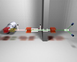
As described in the {\em Facilities} section of this proposal, the Idaho Accelerator has a number of low energy (10's of MeV) electron linacs. We propose to construct a beamline for the production of linearly polarized bremsstrahlung photons modeled after that constructed by the Geissen group. It is well known that when an electron beam strikes a thin radiator, the resulting bremsstrahlung radiation which lies off axis from the incident beam is polarized as shown in figure \ref{fig:polbrems}. If one collimates the photon beam at an angle of $\theta = \frac{m_e}{Ee}$ where $m_e$ is the rest mass of the electron and $E_e$ is the energy of the incident beam, the polarization is maximized. A schematic of the relevant geometry is shown in the figure. The energy dependence of the polarization of such a beam, as measured by a polarimeter which is based on the large analyzing power of the photodisintegration of the deuteron, is shown in figure \ref{fig:pol} where it can be seen that modest polarizations of the bremsstrahlung beam can be obtained. The rate of the photons as compared to the uncollimated case is decreased by approximately a factor of 20 to 30 due to the collimation as well as the need for a thin radiator to minimize multiple scattering of the incident electrons.
\begin{figure}[ht]
\centering
\psfig{figure=pol.eps,height=5.in,width=7.in}
\caption{Polarization as a function of photon energy for the off axis
bremsstrahlung production of linearly polarized photons. Figure is from
\cite{Geissen1987}.}
\label{fig:pol}
\end{figure}
We propose to
construct such a linearly polarized bremsstrahlung beamline and a
polarimeter
to measure its performance,
and to measure the angular dependence of
the photofission
neutron yields as a function of both the bremsstrahlung endpoint
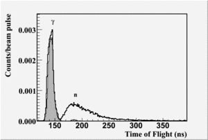
energy and the neutron energy (as determined by time of flight)
to evaluate the sensitivity of this technique to the
presence of photofission events.
\begin{figure}[ht]
\centering
\psfig{figure=Hrrl_valeriia_1.eps,height=5.in,width=7.in}
\caption{}
\label{fig:tony}
\end{figure}
\begin{figure}[ht]
\centering
\psfig{figure=tony.eps,height=5.in,width=7.in}
\caption{}
\label{fig:tony}
\end{figure}
Research Plan Tasks to accomplish scope (35% or 5 pages)
1. establish and commission beamline for polarized photons 2. proof in principle asymm measurement 3. applications: variable targets
(D.Dale)
Milestones and Deliverables
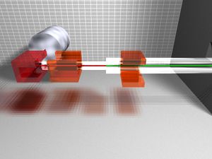
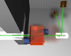
12 months after: acquire beamline components (vacuum pipe for beam dump, beam dump magnet, exit window/pair converter, radiator, 4 PMTs+ bases, octal discriminators, 4-fold logic unit)
24 months after: commission beamline; begin measurements
36 months after: report on measurements with application assessment
R&D resources and Capabilities (10% or 1.5 pages)
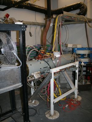
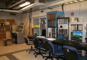
HRRL description (with specs and picture) counting room (with picture)
(V.S.- pictures + T.Forest - description)
Timeline
year 1: establish beamline
year 2:
year 3:
(D.Dale)
Roles of Participants and Team Qualifications (15% or 2 pages)
Participant A = D.Dale = Manager Photofission physics
Participant B = V. Starovoitova = Data analysis expert
Participant C = T. Forest = DAQ, beam line design
Participant D = P. Cole = beamline instrumentation, expert complainer
Students = 2 PhD theses + 2 MS theses, 2 undergrad training
Work Scope Challenges and expected innovations
Documentation procedures
Quality Assurance
Budget form
(V.S. + CV)
