IAC positron beamline
Below are three possible configurations for a positron beam line at the IAC. They are listed in order of increasing complexity and difficulty. Because of the recent winter storm, they are code named using ski trail nomenclature.
Positron beamline
Magnet elements
| Magnet Elements | Label | Thickness (cm) | Current (A) | Resistance (m) | B | Quantity |
| KiwiDipole | D3 & D4 | 30 | ||||
| Q1A | Q1 | 24 | 85 | 53 | 6 T/m | 8 |
| Q1B | Q2 | 24 | 25 | 53 | 9.4 T/m | 7 |
| Q1C | Q3 | 24 | 115 | 82 | 9T/m | 5 |
| Quad2T | Q | 15 | 120 | 27 | 9 T/m | 3 |
| Quad2A | Q | 10 | 102 | 11 | 19 T/m | 12 |
Power Supplies File:TCR.pdf, [1]
| Type | Manufacture | On Shelf | Tested | magnet |
| 10T250 | EMI | 4 | Use 2 for Dipoles | |
| 250T20 | EMI | 6 | Use on Q1As | |
| 20T500 | EMI | 13 | Use on Q1Bs | |
| 40T250 | EMI | 2 | ||
| 80T60 | EMI | 4 |
Beam Line targets and diagnostics
| Device | Z-thickness |
| HKS Viewer | 15 cm |
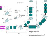
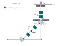
Configuration 1: "Green run"
This configuration is expected to require the minimal amount of effort (3 days) and is to be used as a "test of principle" in order to justify further investment.
The "Green run" configuration proposes switching only two beamline elements. There are three elements between the last two Dipole magnets (D2 & D3) in the beam line. The first element, after a 45 degree bending magnet(D2), is the first quadrupole magnet of a doublet pair. The quadrupole is followed by a quad port for mounting targets and then the second half of the quad doublet just before entering the last 45 degree dipole bending magnet(D3).
The "Green run" configuration would have the first quad of the quad doublet and the target port switch places in the beam line. The target (a Tungsten converter to produce positrons) would be placed just after the first 45 degree dipole. The quad doublet would be positioned after the target and before the last 45 degree bending dipole magnet(D3).
changes
- switch target mount assembly (4-way cross) and quadrupole (3 days)
Goals
The goal of this configuration will be to test positron production efficiencies and determine if the results are scalable by improving the beam line optics.
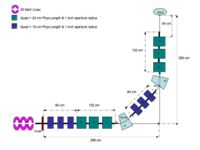
Sketched (not to scale) layout of the 25 MeV beamline:
296 cm = parrallel Distance From the end of the accelerator module (After RF cavities) to experimental cell port
280 cm = Distance From accelerator zero degree beamline to Experimental Cell Wall
56 cm = distance between flanges for the first dipole
84 cm = distance between flanges for the first quad doublet
This configuration looses a lot of positrons due to dispersion before
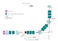
Configuration 2: " Blue run"
This configuration is expected to require a modest amount of effort (1 week) and is to be used as an improved "test of principle" in order to justify further investment.
A new beam line would be built off the zero degree port. The "Blue run" configuration would have the positron converter target positioned just before the first 45 degree dipole bend followed by quads.
File:Positron BlueRun.jpg
changes
- maching new spool pieces
- install control system for the additional quadrupole
- recondition thin quadrupoles to be more water leak resistant and more easily maintained.
Goals
The goals of this configuration would be similar to the "Green run"
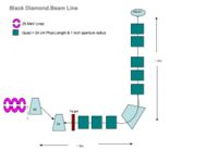
Configuration 3: " Black Diamond"
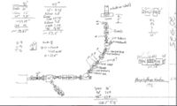
This configuration builds a new beam line which will use the first dipole (D0) currently in place to deflect electrons at 45 degrees beam left. Dipole "D3" will take out the 45 degree deflection of D0 and then send electrons to a 90 degree dipole which will then direct the electrons to the experimental cell through dipole D2 which has been turned off.
A rough measurement suggests that this set up will have as much space as Configuration 4 below, if not more.
Sketched (not to scale) layout of the 25 MeV beamline:
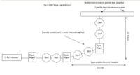
Configuration 4: "Double Black Diamond"
This configuration would require a substantial amount of effort (3 weeks) and would be used as a performance test to determine the maximum positron yield from the 25 MeV linac at the IAC.
changes
- replace the first dipole with 6 quadrupoles
- replace the first 45 degree bending dipole with one that can bend the beam by 45 degree either beam left or beam right. (this will allow us keep the configuration in place and continue experiments which required the first dipole that was removed)
- replace the quad doublet between the last two dipoles with a quad triplet
- install a control system for all the new magnets
Criticisms/problems to solve
- There is not enough room for the target following by 6 quadrupoles. Without the target, quadrupoles 1-6 would occupy 1" more space than what exists. Moving the linac to make space is not a desirable option.
- A magnet to replace the second dipole which would bend the beam +/- 45 degrees as well as allow the beam to pass undeflected would need to be procured
- Additional power supplies for quads 1-6 may need to be procured.
- The thin quadrupoles are difficult to maintain. Specifically, new fittings for the cooling lines would need to be installed which would ease maintenance.
- the proposed beam line changes would require a level of effort similar to moving the Linac in order to fit additional optics elements between the last dipole and the wall
Goal
A complete test of the optimal positron production capabilities using the 25 MeV Linac machine.
Proposed beam line
the above would produce a 1 cm diameter positron beam spot just in front of the wall to the experimental cell.
The mean positron energy would be 2-3 MeV and is tunable.
Magnet pictures
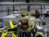
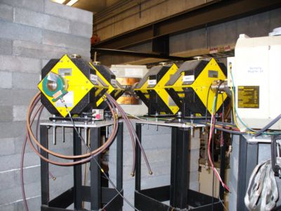
This picture shows you the current 90 degree bend into the experimental hall. Quad 1 and Quad 2 are shown and then the 2nd Dipole magnet (labeled Bending Magnet 2A a.k.a. Dipole 2) begins after Quad 1 and Quad 2. Dipole 2 is following by another Quad doublet and then a Dipole (Dipole 3) and then a final quad doublet before going through the wall into the experimental cell.
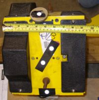
Length of Iron =
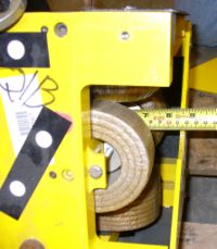
Diameter of Coils=
The next picture was taken upstream of the 90 degree bend and shows Dipole 1 which is usually off unless we want to bend beam right into the accelerator hall instead of going straight to Quad 1 and Quad 2.
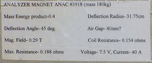
Label on side of Dipole 1
Label on side of Dipole 2
The Quad doublets in the current beam line have the following label.
Quad doublet size:
Beam Monitors
[Viewers from HKS in JLAB's Hall C]
Task List
Parts needed
- target ladder (in/out)
- separate power supply for dipole d2 needs to be installed
Parts in hand
- 1 mm thick tungsten target into cube
- 2 drift chambers
- 2, 1 cm x 2 cm scintillators
- 2, 8 cm x 20 cm scintillators
- 1mm & 2mm thick Tungsten targets
- FC: pico ammeter (100 micro amps to 1 mA)
- Yag scintillatorin viewer(0.1 mRad/hr on contact, 0.06 mRad/hr at 30 cm.) 100 micron thick crystal
- NAI: it fits into the pipe through the wall.
CHIP collaboration meeting Notes 1-11-08
- MOU: Advertisement, talk at Idaho or JLab, teleconferencing, Joint or Bridge.
Optics
5% of the created positrons would be accepted off the target and need to be transported.
Run Plan
- Tuesday: Measure beam properties. With corrector or FC on Translator table
- Wed: NaI measurements
- Thursday: Meet with IAC engineers
- Tune 10 MeV, 100 micoAmp, 100 nsec , 60 Hz, electrons to FC at D1, 6 mm spot size
- (if target ladder) then look tune electrons to viewer aft last quad.
- reverse D2 polarity and look for positrons in NAI (3 MeV for Double escape, 0.511 MeV separation for the others)
- Change current to 1 positron/pulse
- Measure Positron yield as a function of energy by changing D2 and last three quads. (Use aluminum block the cut off electrons).
- Measure Positron beam profile.
- Reverse D2 and quads to measure electron rate.
- ID 0.511 gammas from positron annihilation.
- Bring screens, corrector coils, slow valve
- FC in May, slow valve, QC quads
RUN at IAC on Feb26 2008
The beam spot size of off dipole D1 was measured: CHIPS Run Feb-2008 The spot size measured was after a 1 mm Al-1mm Water-1mm Al window.
CHIPS conference call 3/21/08
Solvable Problems:
1.) JLAB would like beam spot of 1 mm. Measured 8 mm after thick window. Doug reported measuring 3 mm without thick window.
2.) Lowering beam current: 10^8 electrons/pulse desired to produce 1 positron per pulse. Perhaps slits can solve the above problems and then localized lead shielding to reduce backgrounds.
3.) Beam position monitoring. Flags from JLab have arrived Brett will look into installing.
May run on IAC schedule for 27,28,29,30
need cameras for the flags.
Next steps after Feb run:
1.) Optimize develop beam line design. Serkan needs more input about the IAC beam properties.
2.)Proposal is to measure beam properties with flags and FCUP during May 27-30 run. (parts to install beam line flags is critical path defining the run start date).
   a.)Measure beam shape at zero degree port and after 90 degree bend
   b.) install FCUP (2 3/4 flange)
   c.) measure background rates

      i.) one flag has positron converter in experimental cell.
      ii.) dipole on experimental cell side
      iii.) photon veto using scintillators
3.) Future beam line
 a.) perhaps move converter target between dipole
 b.) 50 ns beam pulse may give you +/- 2 MeV spread
