Mathematica Simulation
Setting up Mathematica for DC Theta-Phi Isotropic Cone
We can define the constraints of the plane the DC is in
right = ContourPlot[
   x2 == Cot[29.5 \[Degree]] y + .09156, {y, -1, 1}, {x2, 0, 1.8},
   Frame -> {True, True, False, False},
   PlotLabel -> "Right side limit of DC as a function of X and Y",
   FrameLabel -> {"y (meters)", "x (meters)"}, ContourStyle -> Black,
   PlotLegends -> Automatic];

left = ContourPlot[
   x2 == -Cot[29.5 \[Degree]] y + .09156, {y, -1, 1}, {x2, 0, 1.8},
   Frame -> {True, True, False, False},
   PlotLabel -> "Right side limit of DC as a function of X and Y",
   FrameLabel -> {"y (meters)", "x (meters)"}, ContourStyle -> Black,
   PlotLegends -> Automatic];
We can define the x coordinate of the wires as they cross the midpoint plane as shown earlier.
x0forWires[number_] := .23168 + .01337*(number);
We can define the point midway between two parallel lines as the point where one wire is recorded versus its next highest neighbor
x0forWireMiddles[
   number_] := ((.23168 + .01337*(number)) + (.23168 + .01337*(number \
+ 1)))/2;
All of the conditions dependent on \[Theta] and \[Phi]
\[CapitalDelta]a :=
  FullSimplify[(R Sin[\[Theta] \[Degree]])/
     2 (Csc[65 \[Degree] - \[Theta] \[Degree]] -
      Csc[115 \[Degree] - \[Theta] \[Degree]]), \[Theta] > 0];
e := Sin[25 \[Degree]]/Cos[\[Theta] \[Degree]];
a := FullSimplify[(R Sin[\[Theta] \[Degree]])/
     2 (Csc[65 \[Degree] - \[Theta] \[Degree]] +
      Csc[115 \[Degree] - \[Theta] \[Degree]]), \[Theta] > 0];
rD1 := Simplify[(a e - \[CapitalDelta]a) Tan[
     65 \[Degree]] Cos[\[Theta] \[Degree]], \[Theta] > 0];
rD2 := Simplify[(a e + \[CapitalDelta]a) Tan[
     65 \[Degree]] Cos[\[Theta] \[Degree]], \[Theta] > 0];
xD1 := Simplify[rD1 Cos[\[Phi] \[Degree]]];
yD1 := Simplify[rD1 Sin[\[Phi] \[Degree]]];
zD1 := Simplify[rD1 Cot[\[Theta] \[Degree]], \[Theta] > 0];
xD2 := Simplify[rD2 Cos[\[Phi] \[Degree]], \[Theta] > 0];
yD2 := Simplify[rD2 Sin[\[Phi] \[Degree]], \[Theta] > 0];
zD2 := Simplify[rD2 Cot[\[Theta] \[Degree]], \[Theta] > 0];
xP := Simplify[(R Cos[\[Phi] \[Degree]])/(Cot[\[Theta] \[Degree]] +
      Cos[\[Phi] \[Degree]] Cot[65 \[Degree]]), \[Theta] > 0];
yP := Simplify[(R Sin[\[Phi] \[Degree]])/(Cot[\[Theta] \[Degree]] +
      Cos[\[Phi] \[Degree]] Cot[65 \[Degree]]), \[Theta] > 0];
zP := Simplify[(R Cot[\[Theta] \[Degree]])/(Cot[\[Theta] \[Degree]] +
      Cos[\[Phi] \[Degree]] Cot[65 \[Degree]]), \[Theta] > 0];
x1 := Simplify[(rD2^2 - rD1^2 +
       Cot[\[Theta] \[Degree]]^2 (rD2^2 - rD1^2) - 2 xP (xD2 - xD1) -
       2 yP (yD2 - yD1) - 2 zP (zD2 - zD1))/(4 a e) - a e, \[Theta] >
    0];
x := Simplify[x1 - \[CapitalDelta]a + a e, \[Theta] > 0];
xCenter := x + \[CapitalDelta]a;
n := -957.412/(Tan[\[Theta] \[Degree]] + 2.14437) + 430.626;
D2P := Simplify[((xD2 - xP)^2 + (yD2 - yP)^2 + (zD2 -
       zP )^2)^.5, \[Theta] > 0] // N
D1P := Simplify[((xP - xD1)^2 + (yP - yD1)^2 + (zP -
        zD1)^2)^.5, \[Theta] > 0] // N;
y := Simplify[(D1P^2 - x1^2)^.5, \[Theta] > 0] // N;
b := Simplify[a Sqrt[1 - e^2], \[Theta] > 0] // N;
R = 2.52934271645;
We can define the x-y position on the DC plane as a function of \[Phi] for and limit the angles with the wall on the right and left hand sides. By symmetry these angles are equal, but opposite in sign. The range of \[Phi] in the plane of the DC sector changes as \[Theta] increases, so does \[Phi] increase.
Limits = Table[\[Phi] /.
    NSolve[Sqrt[a^2 (1 - y^2/b^2)] - \[CapitalDelta]a ==
      Cot[29.5 \[Degree]] y + .09156 , \[Phi]], {\[Theta], 5, 40}];
Lim = Table[0, {rows, 1, 36}];
For[rows = 1, rows < 37, rows++,
  For[i = 1, i < 5, i++,
    If[Limits[[rows, i]] > 0 && Limits[[rows, i]] < 40,
      Lim[[rows]] = Limits[[rows, i]];
      ];
    ];
  ];
The angle must have 4 subtracted to equal the line element numbering
In[33]:= Lim[[7 - 4]]

Out[33]= 23.4101
The limit of \[Phi] increases in the plane of the DC sector changes as \[Theta] increases.
In[34]:= Lim[1]

Out[34]= {20.076, 22.024, 23.4101, 24.448, 25.255, 25.9008, 26.4297,
  26.8711, 27.2453, 27.5667, 27.846, 28.0911, 28.3079, 28.5013,
  28.675, 28.8319, 28.9744, 29.1044, 29.2237, 29.3336, 29.4352,
  29.5294, 29.6171, 29.699, 29.7757, 29.8477, 29.9155, 29.9795,
  30.0399, 30.0973, 30.1517, 30.2034, 30.2528, 30.2999, 30.3449,
  30.388}[1]
This limiting condition will record the angle \[Phi] in degrees within an array of wire number(1-112) horizontally and angle \[Theta] (5\[Degree]-40\[Degree]) vertically
RightSolutions =
  Table[{\[Phi] /.
     Solve[Sqrt[a^2 (1 - y^2/b^2)] - \[CapitalDelta]a ==
       Tan[6 \[Degree]] y +
        x0forWireMiddles[number]  , \[Phi]]}, {\[Theta], 5,
    40}, {number, 1, 112}];
LineRight = Table[{\[Phi], columns}, {rows, 1, 36}, {columns, 1, 112}];
For[rows = 1, rows < 37, rows++,
  For[columns = 1, columns < 113, columns++,
    For[i = 1, i < 5, i++,
      If[RightSolutions[[rows, columns, 1, i]] > 0  &&
         RightSolutions[[rows, columns, 1, i]] < Lim[[rows]],
        LineRight[[rows,
           columns]] = {RightSolutions[[rows, columns, 1, i]],
           columns + .5};
        ];
      ];
    ];
  ];
At \[Phi]=0, the condition of n=-959.637/(tan \[Theta]\[Degree] +2.14437)+430.189 should be met
In[38]:= f[\[Theta]for\[Phi]at0_] := -959.637/(
  Tan[\[Theta]for\[Phi]at0 \[Degree]] + 2.14437) + 430.189

In[39]:= f[40]

Out[39]= 108.538
This implies that for \[Theta]=40, we know that the wire number to be 108.538. This corresponds to the position being in between 108.5 and 109.5, hence it falls into the 109 "bin".
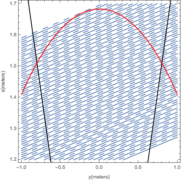
Testing the geometry
ClearAll[\[Theta]];
\[Theta] = 40;
ellipse40 =
  ContourPlot[(x + \[CapitalDelta]a)^2/a^2 + y^2/b^2 == 1, {y, -1,
    1}, {x, 1.2, 1.7}, Frame -> {True, True, False, False},
   PlotLabel ->
    "XY position on DC as a function of \[Phi] for \[Theta]=40\
\[Degree]", FrameLabel -> {"y (meters)", "x (meters)"},
   ContourStyle -> Red, PlotLegends -> Automatic];
Show[Table[
  ContourPlot[
   xWire == Tan[6 \[Degree]] yWire + x0forWires[number], {yWire, -1,
    1}, {xWire, 1.2, 1.7},
   FrameLabel -> {"y(meters)", "x(meters)"}], {number, 70, 109}],
 Table[ContourPlot[
   xWire ==
    Tan[6 \[Degree]] yWire + x0forWireMiddles[number2], {yWire, -1,
    1}, {xWire, 1.2, 1.7},
   ContourStyle -> {Dashing[Large]}], {number2, 70,
   109}], bottom, right, left, ellipse40]
