Difference between revisions of "A W CAA apparatus"
| Line 19: | Line 19: | ||
[[File:Signal_Diagram.png | 600 px]] | [[File:Signal_Diagram.png | 600 px]] | ||
| + | [[File:Signal_Diagram_2.png | 600 px]] | ||
The coincidence counting set-up and modules path are as follows. A source is set atop a base constructed of hydrogen dense blocks. These were chosen to reduce the number of background energy spikes detected. The source is placed an equal distance from decorator A and detector B. | The coincidence counting set-up and modules path are as follows. A source is set atop a base constructed of hydrogen dense blocks. These were chosen to reduce the number of background energy spikes detected. The source is placed an equal distance from decorator A and detector B. | ||
Revision as of 15:10, 29 April 2014
Insert you paragraphs describing the apparatus
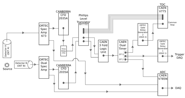
The coincidence counting set-up and modules path are as follows. A source is set atop a base constructed of hydrogen dense blocks. These were chosen to reduce the number of background energy spikes detected. The source is placed an equal distance from decorator A and detector B.
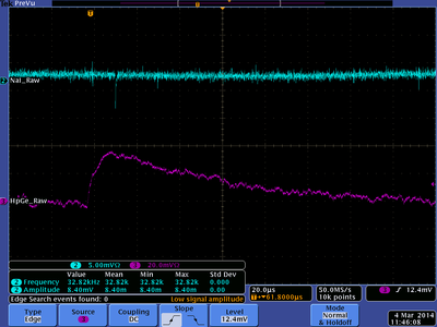
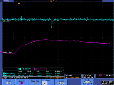
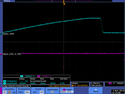
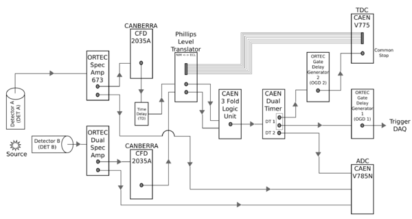
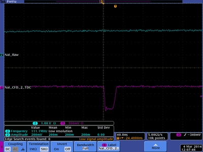
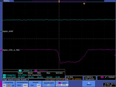
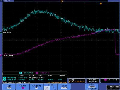
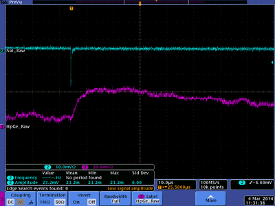
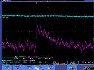
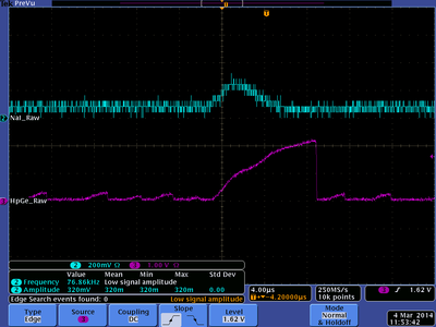
Detector A is positioned directly above the source. A high-purity germanium detector is being utilized for this set-up. The one outgoing signal enters a ORTEC 673 Spectroscopy Amplifier and the outgoing signal then passes through a CANBERRA CFD 2035A. The signal can then enter an optional CAEN CFD to produce a time delay, or can pass directly into a channel (1) of the Level Translator. The second outgoing signal from the Spec Amp goes to a peak sensing CAEN V785N. The output from this module goes to the DAQ.
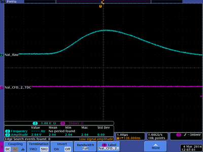
Perpendicular from detector A and placed an equal distance from the source is detector B. This detector can either be a NaI-3 or a germanium detector depending on the source being counted. Detector B’s signal goes to a Post Amplifier and one outgoing signal goes to the above mentioned CAEN V785N and also to the DAQ. The second signal enters a CANBERRA CFD 2035A. The outgoing signal goes to a different channel (4) of the same Level Translator. A ribbon cable on the Level Translator module goes to a Time-to-Digital Converter (TDC) CAEN V775 that is operating in common start mode.
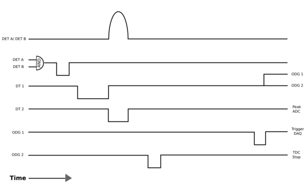
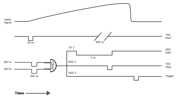
Both channels (1 and 4) of the Level Translator outgoing signal pass to a 3-fold Logic Unit which is used in both OR mode and AND mode to see coincidence lines. This data is collected in the Trig DAQ.
