Difference between revisions of "Detector Operation and DAQ Setup"
| Line 12: | Line 12: | ||
= Data Acquisition (DAQ)= | = Data Acquisition (DAQ)= | ||
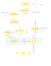
| − | [[Image:QDC_flow_chart.png | | + | [[Image:QDC_flow_chart.png | 100 px]] |
Go Back [https://wiki.iac.isu.edu/index.php/Performance_of_THGEM_as_a_Neutron_Detector#Detector_Description] | Go Back [https://wiki.iac.isu.edu/index.php/Performance_of_THGEM_as_a_Neutron_Detector#Detector_Description] | ||
Revision as of 13:29, 1 July 2013
Detector operation
Operating the detector occurs by providing voltage to the HV-circuit connected to the detector components mentioned in the previous section. A CAEN N470 four channel power supply is used for this purpose, using a channel of the power supply allow to increase the voltage difference between the top and bottom side of the first GEM preamplifier reaches up to 350 V then it decreases for the third GEM preamplifier, as the circuit board is provided with a voltage of 2.8 kV.
Another channel of the power supply is used to increase the voltage of the Cathode. When the cathode voltage is 3.1 kV, it will create a drift voltage up to 300V.
The power supply is connected to a discharge protection circuit. CAEN N470 has a signal Lemo 00 input to activate a kill option automatically when a discharge signal occurs through the detector operation, the kill input is connected to the detector readout plate output, as a discharge happens and it is wider than 15 us, kill option state turns true, so it will trip all the power supply channels.
Data Acquisition (DAQ)
Go Back [1]

