Difference between revisions of "Sadiq IPAC 2012"
| Line 16: | Line 16: | ||
{| border="0" style="background:transparent;" align="center" | {| border="0" style="background:transparent;" align="center" | ||
|- | |- | ||
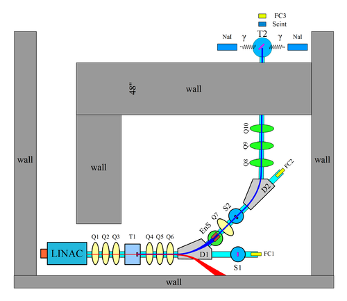
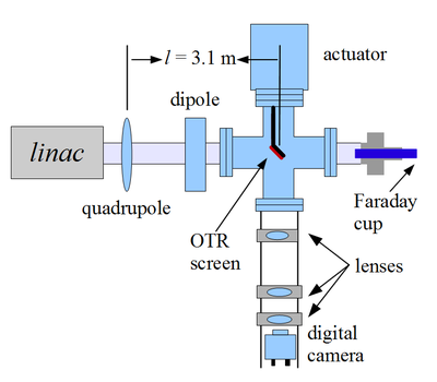
| − | | | + | | [[image:BeamLine_Yim_10-14-10.png | 500 px |thumb|Fig. HRRL beamline.]] || [[image:hrrl_2011_mar_emit_test_quad_scan_quad.png | 400 px |thumb|Fig. Imaging system for HRRL.]] |
| − | [[image:BeamLine_Yim_10-14-10.png | 500 px |thumb|Fig. HRRL beamline.]] || [[image:hrrl_2011_mar_emit_test_quad_scan_quad.png | 400 px |thumb|Fig. Imaging system for HRRL.]] | ||
|} | |} | ||
Revision as of 05:43, 3 November 2011
Emittance Measurement of Varian Medical Linac
Abstract
Emittance of Varian High Rep-Rate Linac (HRRL) was measured with Optical Transition Radiation (OTR) at 14 MeV. Electron beam was observed at 10 thick Al screen. Projection of beam appear to be sharper than Gaussian distribution, and super-Gaussian distribution were fitted. Quadrupole scanning method shows that horizontal and vertical are and respectively.
Introduction
Experiment Setup
Experimental setup is shown in the following two figures.
We chose one of the quad at a time to do the scan and turned off all the other quads. Optical transition radiation was observed at OTR target. At the end of 0 degree beamline we have a Faraday cup to measure the charge of the beam. Camera cage system was located below the OTR target. There are 3 lenses used to focus lights from target to the CCD camera. Target can be pushed into or taken out of the beamline by the actuator at the top.

