Difference between revisions of "Tamar Electron and Pion Efficiency"
| Line 80: | Line 80: | ||
=Semi-Inclusive Efficiency= | =Semi-Inclusive Efficiency= | ||
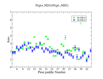
| − | In this chapter we discuss the pion efficiency in semi-inclusive case. The ratio of the pions is shown on Fig. 4.1. | + | In this chapter we discuss the pion efficiency in semi-inclusive case. The ratio of the pions detected in the scintillator paddles, located between the Cherenkov counter and electromagnetic calorimeter, is shown on Fig. 4.1. The ratios were taken for four different cases. Assuming that, for the inbending case positive pions and for the outbending case have the same trajectories(the same kinematics) and vice versa((the inbending,negative pion) and (the outbending, positive pions)).<br> |
[[File:paddenumbvsratio.jpg|500px]]<br> | [[File:paddenumbvsratio.jpg|500px]]<br> | ||
Revision as of 21:22, 6 June 2011
Particle ID
The correct identification of an electron and a pion is the main requirement for a semi-inclusive analysis. unfortunately, the pion is able to generate cerenkov radiation an as a result be misidentified as an electron. This contamination of the electron sample is removed using the cuts on the energy deposited in the electromagnetic calorimeter, the number of photoelectrons in the Cherenkov counter and fiducial cuts on the detector acceptance.
The energy deposition in the calorimeter for electrons and pions is different. Pions are minimum ionizing charge particles depositing into the calorimeter which is independent of the pion's momentum once the momentum is above ~ 0.08 GeV. On the other hand, electrons produce photoelectrons and create electromagnetic shower releasing the energy into the calorimeter which is proportional to their momentum. In order to remove contamination due to the energy deposition in the calorimeter the following cut was introduced: . The cut was also applied to the energy collected in the inner part of the calorimeter: , because the ratio of the energy deposited in the total to the inner calorimeter depends on the thickness of the detector and is a constant.
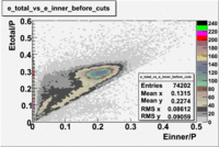
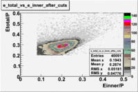
Figure 1.1. The energy deposition into the total and inner calorimeter before and after cuts.
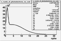
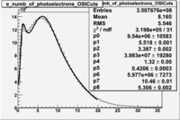
In addition to the cut on the energy deposited into the electromagnetic calorimeter, the misidentified electrons were excluded requiring a signal in the threshold CLAS Cherenkov detector. Pion's misidentified as electrons have been shown to produce around ~1.5 photoelectons in the cherenkov detector, as shown below. Geometrical cuts on the location of the particle at the entrance to the cerenkov detector were applied to reduce the pion contamination. The second histogram below shows that after cuts the peak around 1.5 is substantially reduced.
| No cuts | OSI Cuts |
Figure 1.2. The number of photoelectrons before and after cuts.
Exlusive
The differential cross-section and asymmetries were measured using the CLAS with a 5.7 GeV continuous electron beam of luminosity when using the polarized targets above. A comparison was made with the results from experiment E99-107<ref name="Park2008" >Park, K., Burkert, V. D., & Kim, W. (The CLAS Collaboration). (2008). Cross sections and beam asymmetries for -> in the nucleon resonance region for . Phys. Rev., C77, 015208.</ref> in order to validate our semi-inclusive analysis.
Experiment E99-107 measured exclusive pion production using a liquid hydrogen target and the CLAS.
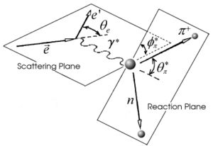
The kinematics of single pion electroproduction can be described by five variables: the virtual photon negative four-momentum transfered squared , W invariant mass of the photon-nucleon system, the polar and the azimuthal angle of the outgoing pion in center of mass frame and the scattered electron azimuthal angle.
The five-fold differential cross section can be written in the following way for a single pion electroproduction:
where - the integrated luminosity, is the acceptance factor, represents the efficiency of the cherenkov detector and the Jacobian term can be expressed in terms of the initial and final energy of lepton:
Because of wide range of kinematics, was measured only for certain lepton scattering angles and invariant mass (W). Applying above described cuts: EC_inner>0.06, EC_tot/p>0.2, nphe>2.5 and , for the following invariant mass and the vs relative rate distribution is shown below on the graph and compared with E99-107 data, which by itself is in agreement with the models.
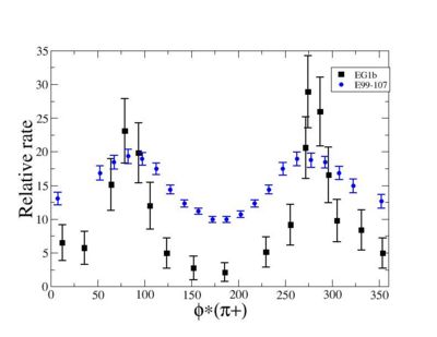 Figure 2.2. vs Relative rate for fixed and <ref name="Park2008" > Bogus text</ref> <ref> http://clasweb.jlab.org/cgi-bin/clasdb/msm.cgi?eid=14&mid=16&data=on </ref> |
The EG1b data for kinematics chosen above show the same shape as E99-107 data.
Inclusive Efficiency
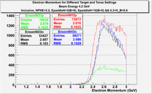
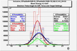
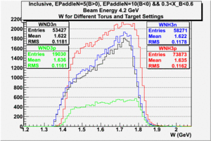
In this chapter we describe the electron paddle number selection and electron efficiency. The analysis were performed on 4.2 GeV data for ND3 and NH3 targets. In the final state, only electron detection was required(inclusive case). The contamination in the electron sample was removed by applying cuts described in the first chapter. The histograms on Fig. 3.1 represent the scattered electron paddle number for both types of target. The electron paddle number 10 and 5 were chosen for B<0 and B>0 respectively. The kinematics(Momentum, scattering angle and invariant mass) for selected electron paddle numbers are shown on Fig. 3.2.
| Target Type, Polarity, Beam Energy | Electron Paddle Number |
| ND3, B<0, 4.2 GeV | 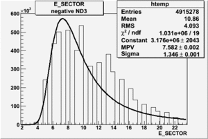
|
| ND3, B>0, 4.2 GeV | 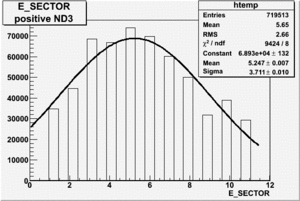
|
| NH3, B<0, 4.2 GeV | 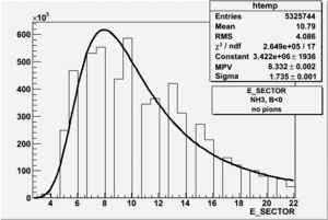
|
| NH3, B>0, 4.2 GeV | 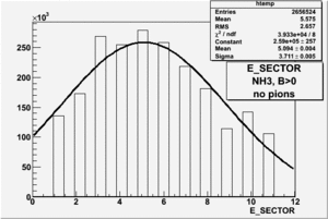
|
Figure 3.1. Electron Paddle Number for NH3 and ND3 targets.
 |
 |
|
| Electron Momentum((NH3,B>0), (NH3,B<0), (ND3,B>0) && (ND3,B<0)) | Electron Scattering Angle ((NH3,B>0), (NH3,B<0), (ND3,B>0) && (ND3,B<0)) | W Invariant mass((NH3,B>0), (NH3,B<0), (ND3,B>0) && (ND3,B<0)) |
Figure 3.1. Electron Kinematics.
The ratio of the number of electrons weighted by the faraday cup for two different cases are following:
In order to make the ratio unity, each of the two cases need to be multiplied by "correction coefficient". The coefficient for the case is and for the it is .
Semi-Inclusive Efficiency
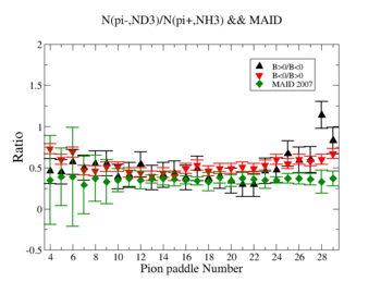
In this chapter we discuss the pion efficiency in semi-inclusive case. The ratio of the pions detected in the scintillator paddles, located between the Cherenkov counter and electromagnetic calorimeter, is shown on Fig. 4.1. The ratios were taken for four different cases. Assuming that, for the inbending case positive pions and for the outbending case have the same trajectories(the same kinematics) and vice versa((the inbending,negative pion) and (the outbending, positive pions)).
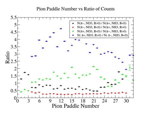
Figure 4.1. Pion paddle number vs Ratio.
We used MAID 2007 model to compare our results. Total cross section was calculated for the following invariant mass and four momentum transferred square: and .
where
is pion azimuthal angle in CM frame, - virtual photon polarization.
where , (the difference between the initial and final energy of the electron).
- Four momentum transferred square.
- electron scattering angle.
h - electron helicity.
Figure 4.2. Pion paddle number vs Ratio after correction.
Notes
<references/>
