Difference between revisions of "Lab 14 RS"
| Line 28: | Line 28: | ||
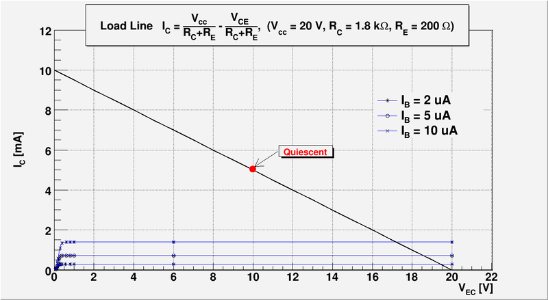
3.)Draw a load line using the <math>I_{C}</math> -vs- <math>I_{CE}</math> from the previous lab 13. Record the value of <math>h_{FE}</math> or <math>\beta</math>. | 3.)Draw a load line using the <math>I_{C}</math> -vs- <math>I_{CE}</math> from the previous lab 13. Record the value of <math>h_{FE}</math> or <math>\beta</math>. | ||
| + | |||
| + | [[File:Load Line 10mA.png | 800 px]] | ||
| + | |||
4.)Set a DC operating point <math>I^{\prime}_C</math> so it will amplify the input pulse given to you. Some of you will have sinusoidal pulses others will have positive or negative only pulses. | 4.)Set a DC operating point <math>I^{\prime}_C</math> so it will amplify the input pulse given to you. Some of you will have sinusoidal pulses others will have positive or negative only pulses. | ||
Revision as of 04:29, 20 March 2011
The Common Emitter Amplifier
Circuit
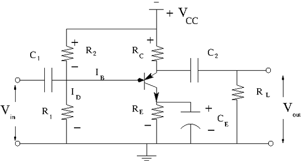
1.)Construct the common emitter amplifier circuit below according to your type of emitter.
2.)Calculate all the R and C values to use in the circuit such that
- a. Try and
- b. mA DC with no input signal
- c. V
- d. to prevent burnout
- e.
- f. mA
Let's , and . The load line equation becomes:
This load line pretty high and give me the wide range of amplification the input signal.
3.)Draw a load line using the -vs- from the previous lab 13. Record the value of or .
4.)Set a DC operating point so it will amplify the input pulse given to you. Some of you will have sinusoidal pulses others will have positive or negative only pulses.
5.)Measure all DC voltages in the circuit and compare with the predicted values.(10 pnts)
6.)Measure the voltage gain as a function of frequency and compare to the theoretical value.(10 pnts)
7.)Measure and at about 1 kHz and compare to the theoretical value.(10 pnts)
How do you do this? Add resistor in front of which you vary to determine and then do a similar thing for except the variable reistor goes from to ground.
8.)Measure and as a function of frequency with removed.(10 pnts)
Questions
- Why does a flat load line produce a high voltage gain and a steep load line a high current gain? (10 pnts)
- What would be a good operating point an an common emitter amplifier used to amplify negative pulses?(10 pnts)
- What will the values of , , and be if the transistor burns out resulting in infinite resistance. Check with measurement.(10 pnts)
- What will the values of , , and be if the transistor burns out resulting in near ZERO resistance (ie short). Check with measurement.(10 pnts)
- Predict the change in the value of if is increased from 10 to 50 (10 pnts)
- Sketch the AC equivalent circuit of the common emitter amplifier.(10 pnts)
Go Back to All Lab Reports Forest_Electronic_Instrumentation_and_Measurement

