Difference between revisions of "TF EIM Chapt3"
Jump to navigation
Jump to search
| Line 7: | Line 7: | ||
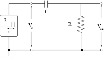
[[File:TF_EIM_PulsedRCHighpass.png | 400 px]] | [[File:TF_EIM_PulsedRCHighpass.png | 400 px]] | ||
| + | |||
| + | The first thing to consider is what happens to the different parts of the square pulse as it travels to the circuit. | ||
| + | |||
| + | You know that the circuit, as a high pass filter, will tend to attenuate low frequency (slow changing) voltages and not high frequency (quick changing) voltages. | ||
| + | |||
| + | This means that points a and b in the pulse shown below should pass through the | ||
=Integrator= | =Integrator= | ||
Revision as of 16:51, 8 February 2011
Differentiator circuit
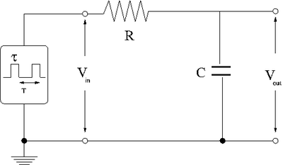
Consider the effect of a low-pass filter on a rectangular shaped input pulse with a width and period .
The first thing to consider is what happens to the different parts of the square pulse as it travels to the circuit.
You know that the circuit, as a high pass filter, will tend to attenuate low frequency (slow changing) voltages and not high frequency (quick changing) voltages.
This means that points a and b in the pulse shown below should pass through the

