Difference between revisions of "Lab 5 RS"
Jump to navigation
Jump to search
| Line 1: | Line 1: | ||
[https://wiki.iac.isu.edu/index.php/Electronics_RS Go Back to All Lab Reports] | [https://wiki.iac.isu.edu/index.php/Electronics_RS Go Back to All Lab Reports] | ||
| + | |||
;LC Resonance circuits | ;LC Resonance circuits | ||
Revision as of 17:10, 2 February 2011
- LC Resonance circuits
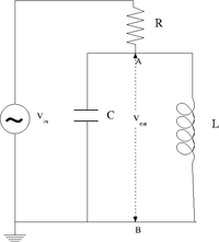
The LC circuit
Design a parallel LC resonant circuit with a resonant frequency between 50-200 kHz. use = 10 - 100 , R = 1k
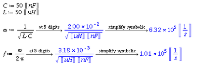
I choose the following values for and :
So the resonance frequency is
Or
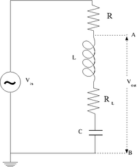
Let's estimate:
Construct the LC circuit using a non-polar capacitor
Measure the Gain as a function of frequency. (25 pnts)
Compare the measured and theoretical values of the resonance frequency () (10 pnts)
Questions
1.Is there a value of in which at resonance. What is the value?(5 pnts)


