|
|
| Line 30: |
Line 30: |
| ==Questions== | | ==Questions== |
|
| |
|
| #Is there a value of <math>R</math> in which <math>V_{out} \approx V_{in}</math> at resonance. What is the value?(5 pnts)
| | ===Is there a value of <math>R</math> in which <math>V_{out} \approx V_{in}</math> at resonance. What is the value?(5 pnts)=== |
|
| |
|
| =The RLC cicuit= | | =The RLC cicuit= |
| [[File:TF_EIM_Lab5_RLC.png| 200 px]] | | [[File:TF_EIM_Lab5_RLC.png| 200 px]] |
| #Design and construct a '''series''' LRC circuit.
| | ==Design and construct a '''series''' LRC circuit== |
| #Measure and Graph the Gain as a function of the oscillating input voltage frequency. (25 pnts)
| | ==Measure and Graph the Gain as a function of the oscillating input voltage frequency. (25 pnts)== |
| #Measure and Graph the Phase Shift as a function of the oscillating input voltage frequency. (25 pnts)
| | ==Measure and Graph the Phase Shift as a function of the oscillating input voltage frequency. (25 pnts)== |
| ==Questions== | | ==Questions== |
| #What is the current <math>I</math> at resonance? (5 pnts)
| | ===What is the current <math>I</math> at resonance? (5 pnts)=== |
| #What is the current as <math>\nu \rightarrow \infty</math>? (5 pnts)
| | ===What is the current as <math>\nu \rightarrow \infty</math>? (5 pnts)=== |
| | |
| | |
| | |
| | |
| | |
| | |
| ;LC Resonance circuits
| |
| =The LC cicuit=
| |
| [[File:TF_EIM_Lab5_LC.png| 200 px]]
| |
| ==Design a '''parallel''' LC resonant circuit with a resonant frequency between 50-200 kHz. use <math>L</math> = 10 - 100 <math>\mu H</math>.==
| |
| | |
| :<math>\omega_0=\frac{1}{\sqrt{\mbox{LC}}}</math>
| |
| | |
| I choose the following values for <math>\mbox{R}</math> and <math>\mbox{C}</math>:
| |
| | |
| :<math>R=aaa\ \Omega</math>
| |
| :<math>C=bbb\ \mu F</math>
| |
| | |
| So the resonance frequency is <math>\omega_0=\frac{1}{\sqrt{aaa\ \Omega\ bbb\ \mu F }} = ccc\ \frac{\mbox{rad}}{\mbox{sec}}</math>
| |
| | |
| Or <math>f=\frac{\omega_0}{2\pi} = ddd\ \mbox{kHz}</math>
| |
| | |
| | |
| Let's estimate:
| |
| | |
| [[File:L4 LC.png | 400 px]]
| |
| | |
| ==Construct the LC circuit using a non-polar capacitor==
| |
| ==Measure the Gain <math>\equiv \frac{V_{out}}{V_{in}}</math> as a function of frequency. (20 pnts)==
| |
| ==Measure the Gain when an external resistance approximately equals to the inherent resistance of the rf choke <math>R_{L}</math>. (20 pnts)==
| |
| ==Compare the measured and theoretical values from the resonance frequency (<math>\omega_{L}</math>) and the Quality factor <math>Q \equiv 2 \pi \frac{W_S}{W_L} = 2 \pi \frac{\mbox{Energy Stored}}{\mbox{Energy Lost}}</math> value for each case; <math>W = \frac{1}{2}LI^2</math>. (10 pnts)==
| |
| | |
| ==Questions==
| |
| | |
| #If r=0, show that <math>Q = \frac{1}{\omega_0 R_L C}</math>. (10 pnts)
| |
| #Show that at resonance<math> Z_{AB} \approx Q \omega_0 L</math>. (10 pnts)
| |
| | |
| =The LRC cicuit=
| |
| [[File:TF_EIM_Lab5_RLC.png| 200 px]]
| |
| #Design and construct a '''series''' LRC circuit.
| |
| #Measure and Graph the Gain as a function of the oscillating input voltage frequency. (20 pnts)
| |
| ==Questions==
| |
| #What is the current <math>I</math> at resonance? (5 pnts)
| |
| #What is the current as <math>\nu \rightarrow \infty</math>? (5 pnts)
| |
|
| |
|
|
| |
|
Go Back to All Lab Reports
- LC Resonance circuits
The LC cicuit
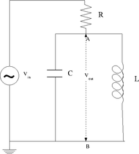 ==Design a parallel LC resonant circuit with a resonant frequency between 50-200 kHz. use [math]\displaystyle{ L }[/math] = 10 - 100 [math]\displaystyle{ \mu H }[/math], R = 1k
[math]\displaystyle{ \Omega }[/math]==
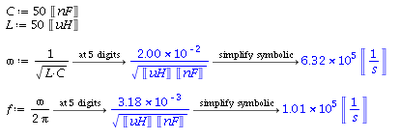
- [math]\displaystyle{ \omega_0=\frac{1}{\sqrt{\mbox{LC}}} }[/math]
I choose the following values for [math]\displaystyle{ \mbox{R} }[/math] and [math]\displaystyle{ \mbox{C} }[/math]:
- [math]\displaystyle{ R=aaa\ \Omega }[/math]
- [math]\displaystyle{ C=bbb\ \mu F }[/math]
So the resonance frequency is [math]\displaystyle{ \omega_0=\frac{1}{\sqrt{aaa\ \Omega\ bbb\ \mu F }} = ccc\ \frac{\mbox{rad}}{\mbox{sec}} }[/math]
Or [math]\displaystyle{ f=\frac{\omega_0}{2\pi} = ddd\ \mbox{kHz} }[/math]
Let's estimate:
Construct the LC circuit using a non-polar capacitor
Measure the Gain [math]\displaystyle{ \equiv \frac{V_{out}}{V_{in}} }[/math] as a function of frequency. (25 pnts)
#Compare the measured and theoretical values of the resonance frequency ([math]\displaystyle{ \omega_{L} }[/math]) (10 pnts)
Questions
Is there a value of [math]\displaystyle{ R }[/math] in which [math]\displaystyle{ V_{out} \approx V_{in} }[/math] at resonance. What is the value?(5 pnts)
The RLC cicuit
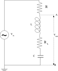
Design and construct a series LRC circuit
Measure and Graph the Gain as a function of the oscillating input voltage frequency. (25 pnts)
Measure and Graph the Phase Shift as a function of the oscillating input voltage frequency. (25 pnts)
Questions
What is the current [math]\displaystyle{ I }[/math] at resonance? (5 pnts)
What is the current as [math]\displaystyle{ \nu \rightarrow \infty }[/math]? (5 pnts)
Forest_Electronic_Instrumentation_and_Measurement
Go Back to All Lab Reports
 ==Design a parallel LC resonant circuit with a resonant frequency between 50-200 kHz. use [math]\displaystyle{ L }[/math] = 10 - 100 [math]\displaystyle{ \mu H }[/math], R = 1k
[math]\displaystyle{ \Omega }[/math]==

