Difference between revisions of "TF EIMLab1 Writeup"
| Line 65: | Line 65: | ||
|Variable ||Measured Value|| Predicted Value|| % Difference | |Variable ||Measured Value|| Predicted Value|| % Difference | ||
|- | |- | ||
| − | | <math>V_B</math> || 103.5 mV || 156 || 50% | + | | <math>V_B</math> || 103.5 +/- 50 mV || 156 || 50% |
|- | |- | ||
| <math>I_1</math> || 20.4 mA ||22 || 7% | | <math>I_1</math> || 20.4 mA ||22 || 7% | ||
Revision as of 20:15, 12 January 2011
Kirchoff's Law (50 pnts)
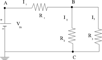
Construct the circuit below
Enter the values of the DC voltage and Resisters that you used.
Use a voltmeter to measure the potential difference and resistances.
| Variable | Measured Value |
| 20 Volts | |
| 902 | |
| 10.2 | |
| 10.6 |
Enter the measured and predicted quantities in the table below
Given and the values of all resistors, use Kirchoff's laws to predict
a.) Predict the value of
I_1 =?
Kirchoff's Loop theorem (Voltage Law)
where R =resistance for and in series.
mV
b.) Predict the values of the three currents.
I
2 equations and 2 unkowns
mA
mA
c.) compare your predictions and measurements by filling in the table below.
| Variable | Measured Value | Predicted Value | % Difference |
| 103.5 +/- 50 mV | 156 | 50% | |
| 20.4 mA | 22 | 7% | |
| 9.5 mA | 11.2 | 18% | |
| 9.0 mA | 10.8 | 20% |
Internal resistance (30 pnts)
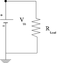
Measure the internal resistance of your power source by graphing the potential difference on the x-axis and the current on the y-axis for several values of the resistance shown in the circuit below. Begin with and then decrease it by a factor of 5 for each subsequent measurement. You can use a volt meter to measure the current and potential difference.
| R_{Load} () | V (Volts) | I (mA) |
| 10 | 1.42 0.06 | 118 3 |
| 93 | 1.55 0.01 | 16.15 0.05 |
| 990 | 1.575 0.005 | 1.54 0.04 |
| 10110 | 1.579 0.005 | 0.146 0.005 |
| 15060 | 1.579 0.005 | 0.101 0.003 |
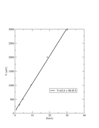
Below I set R= 95 and changed V
| V (mv) | I (mA) |
| 126.1 | 0.79 |
| 300 | 2.64 |
| 500 | 4.62 |
| 1000 | 9.29 |
| 2000 | 18.78 |
| 3000 | 30.4 |
Now lets try to fix V and change R
Questions (20 pnts)
- What conservation law is involved in Kirchoff's Loop Theorem?
- What does the slope in the internal resistance plot above represent?


