Difference between revisions of "TDC Calibration"
Jump to navigation
Jump to search
| Line 11: | Line 11: | ||
Range of all three TDCs was set to 50nsx100. | Range of all three TDCs was set to 50nsx100. | ||
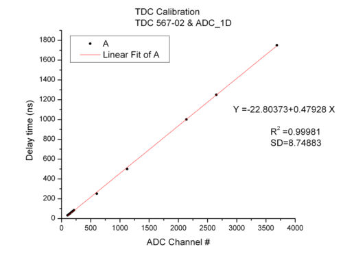
| − | =ORTEC 567-02 and ADC 1D= | + | =ORTEC TAC 567-02 and ADC 1D= |
[[Image:567_02.jpg |500px]] | [[Image:567_02.jpg |500px]] | ||
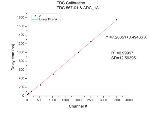
| − | =ORTEC 567-01 and ADC 1A= | + | =ORTEC TAC 567-01 and ADC 1A= |
[[Image:567_01.jpg |500px]] | [[Image:567_01.jpg |500px]] | ||
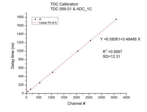
| − | =ORTEC 566-01 and ADC 1C= | + | =ORTEC TAC 566-01 and ADC 1C= |
[[Image:566_01.jpg |500px]] | [[Image:566_01.jpg |500px]] | ||
Revision as of 03:30, 7 November 2008
We used:
-detector A to calibrate all the TDCs;
-LeCroy octal discriminator to produce standard negative pulses;
-passive delay line to calibrate TDCs in the region < 100 ns;
-delay amplifier TENNELEC TC215 to calibrate TDCs in the region > 250 ns;
Range of all three TDCs was set to 50nsx100.


