Difference between revisions of "Metalica TestPulseoutput 12-20-07"
| Line 11: | Line 11: | ||
We observed the ouput of a test pule injected into the preamp for several preamp voltage setting. The top (purple) trace is the injected pulse and the bottom (torquoise) trace is the output from the POSTamp. | We observed the ouput of a test pule injected into the preamp for several preamp voltage setting. The top (purple) trace is the injected pulse and the bottom (torquoise) trace is the output from the POSTamp. | ||
| − | + | {| border="1" cellpadding="20" cellspacing="0" | |
| − | [[Image:metalica_160mv_input-postamp_out_3.7v.jpg|200px]] | + | |- |
| − | [[Image:metalica_160mv_input-postamp_out_5v.jpg|200px]] | + | |Preamp Voltage(Volts) |
| − | [[Image:metalica_160mv_input-postamp_out_5.1v.jpg|200px]] | + | | |
| − | [[Image:metalica_160mv_input-postamp_out_5.2v.jpg|200px]] | + | |- |
| − | [[Image:metalica_160mv_input-postamp_out_5.3v.jpg|200px]] | + | |3.7 || [[Image:metalica_160mv_input-postamp_out_3.7v.jpg|200px]] |
| − | [[Image:metalica_160mv_input-postamp_out_5.4v.jpg|200px]] | + | |- |
| − | [[Image:metalica_160mv_input-postamp_out_5.5v.jpg|200px]] | + | |5 || [[Image:metalica_160mv_input-postamp_out_5v.jpg|200px]] |
| − | [[Image:metalica_160mv_input-postamp_out_5.6v.jpg|200px]] | + | |- |
| − | [[Image:metalica_160mv_input-postamp_out_5.7v.jpg|200px]] | + | |5.1 || [[Image:metalica_160mv_input-postamp_out_5.1v.jpg|200px]] |
| − | [[Image:metalica_160mv_input-postamp_out_5.8v.jpg|200px]] | + | |- |
| − | [[Image:metalica_160mv_input-postamp_out_6v.jpg|200px]] | + | |5.2 || [[Image:metalica_160mv_input-postamp_out_5.2v.jpg|200px]] |
| + | |- | ||
| + | |5.3 || [[Image:metalica_160mv_input-postamp_out_5.3v.jpg|200px]] | ||
| + | |- | ||
| + | |5.4 || [[Image:metalica_160mv_input-postamp_out_5.4v.jpg|200px]] | ||
| + | |- | ||
| + | |5.5 || [[Image:metalica_160mv_input-postamp_out_5.5v.jpg|200px]] | ||
| + | |- | ||
| + | |5.6 || [[Image:metalica_160mv_input-postamp_out_5.6v.jpg|200px]] | ||
| + | |- | ||
| + | |5.7 || [[Image:metalica_160mv_input-postamp_out_5.7v.jpg|200px]] | ||
| + | |- | ||
| + | |5.8 || [[Image:metalica_160mv_input-postamp_out_5.8v.jpg|200px]] | ||
| + | |- | ||
| + | |6 || [[Image:metalica_160mv_input-postamp_out_6v.jpg|200px]] | ||
| + | |} | ||
[http://www.iac.isu.edu/mediawiki/index.php/Mini-prototype#Post_Amp_NIM_Module] | [http://www.iac.isu.edu/mediawiki/index.php/Mini-prototype#Post_Amp_NIM_Module] | ||
Revision as of 17:16, 21 December 2007
I test the DC preamp + postamp output using a pulse generator to create a 40 mV levelpulse that was 10 ns wide in order to simulate a pulse from the drift chamber proto-type.
This time we used Metalica but the results are not so different.
The bottom line appears to be that we get a x4 attenuation and not a net amplification deispite our efforts the change the configuration for the better. We also note that channels 1-11 of the postamp proto type attenuate by a factor of four but channels 12-16 have a signal independent of the input.
The voltage was changed
PreAmp Voltage
We observed the ouput of a test pule injected into the preamp for several preamp voltage setting. The top (purple) trace is the injected pulse and the bottom (torquoise) trace is the output from the POSTamp.
| Preamp Voltage(Volts) | |
| 3.7 | 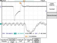
|
| 5 | 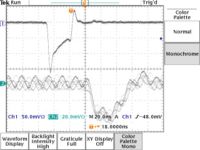
|
| 5.1 | 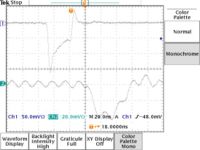
|
| 5.2 | 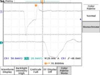
|
| 5.3 | 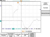
|
| 5.4 | 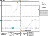
|
| 5.5 | 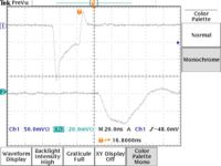
|
| 5.6 | 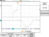
|
| 5.7 | 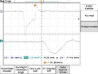
|
| 5.8 | 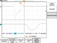
|
| 6 | 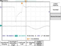
|