Difference between revisions of "IAC positron beamline"
| Line 1: | Line 1: | ||
| − | |||
Below are three possible configurations for a positron beam line at the IAC. They are listed in order of increasing complexity and difficulty and named analogously using ski trail nomenclature. | Below are three possible configurations for a positron beam line at the IAC. They are listed in order of increasing complexity and difficulty and named analogously using ski trail nomenclature. | ||
| Line 10: | Line 9: | ||
Sketched (not to scale) layout of the 25 MeV beamline: | Sketched (not to scale) layout of the 25 MeV beamline: | ||
| − | [[Image:25MeV_IAC.JPG | 50 px ]] | + | [[Image:25MeV_IAC.JPG | 50 px]] |
296 cm = parrallel Distance From the end of the accelerator module (After RF cavities) to experimental cell port | 296 cm = parrallel Distance From the end of the accelerator module (After RF cavities) to experimental cell port | ||
| Line 19: | Line 18: | ||
84 cm = distance between flanges for the first quad doublet | 84 cm = distance between flanges for the first quad doublet | ||
| − | |||
= Configuration 2: " Blue run" = | = Configuration 2: " Blue run" = | ||
Revision as of 17:15, 12 December 2007
Below are three possible configurations for a positron beam line at the IAC. They are listed in order of increasing complexity and difficulty and named analogously using ski trail nomenclature.
Configuration 1: "Green run"
This configuration is expected to require the minimal mount of effort (3 days) and is to be used as a "test of principle" in order to justify further investment.
Sketched (not to scale) layout of the 25 MeV beamline:
296 cm = parrallel Distance From the end of the accelerator module (After RF cavities) to experimental cell port
280 cm = Distance From accelerator zero degree beamline to Experimental Cell Wall
56 cm = distance between flanges for the first dipole
84 cm = distance between flanges for the first quad doublet
Configuration 2: " Blue run"
This configuration is expected to require a modest amount of effort (1 week) and is to be used as improved "test of principle" in order to justify further investment.
= Configuration 3: "Double Black Diamond"
This configuration is would require a substantial amount of effort (3 weeks) and is to be used as a performance test to determine the maximum positron yield from the 25 MeV linac at the IAC.
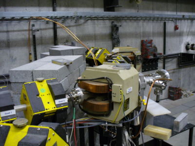
This picture shows you the current 90 degree bend into the experimental hall. Quad 1 and Quad 2 are shown and then the 2nd Dipole magnet (labeled Bending Magnet 2A a.k.a. Dipole 2) begins after Quad 1 and Quad 2. Dipole 2 is following by another Quad doublet and then a Dipole (Dipole 3) and then a final quad doublet before going through the wall into the experimental cell.
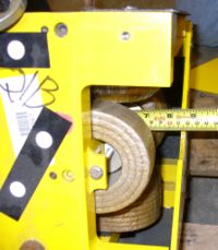
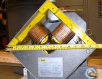
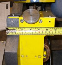
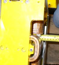
Length of Iron =
Diameter of Coils=
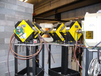
The next picture was taken upstream of the 90 degree bend and shows Dipole 1 which is usually off unless we want to bend beam right into the accelerator hall instead of going straight to Quad 1 and Quad 2.
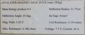
Label on side of Dipole 1
Label on side of Dipole 2
The Quad doublets in the current beam line have the following label.
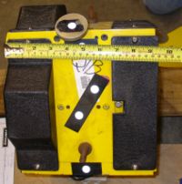
Quad doublet size:
We also have Quad triplet which take up less space than the doubles.
