Difference between revisions of "MiniDC PreampOutput 10 10 07"
| Line 1: | Line 1: | ||
= Preamp output = | = Preamp output = | ||
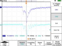
| − | The following scope pictures were taken as the preamp board was being powered on. The Drift chamber High Voltage was off but all cabling (grounds) were conencted. | + | The following scope pictures were taken as the preamp board was being powered on(sense wire 7). The Drift chamber High Voltage was off but all cabling (grounds) were conencted. |
{| border="1" cellpadding="20" cellspacing="0" | {| border="1" cellpadding="20" cellspacing="0" | ||
|- | |- | ||
Revision as of 17:21, 16 October 2007
Preamp output
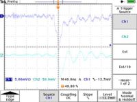
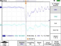
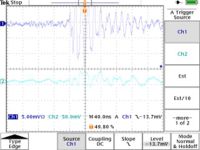
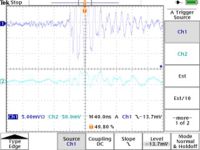
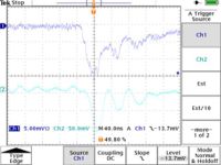
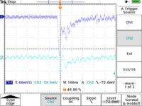
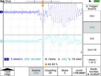
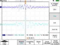
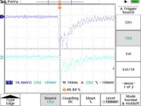
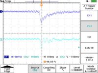
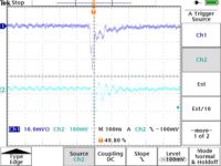
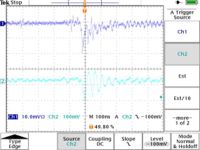
The following scope pictures were taken as the preamp board was being powered on(sense wire 7). The Drift chamber High Voltage was off but all cabling (grounds) were conencted.
| Preamp Board Voltage (Volts) | Scope Image |
| 3.1 | 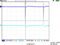 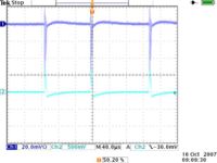
|
| 3.2 | 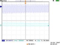 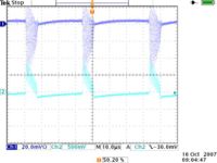 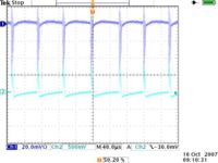
|
| 3.5 | 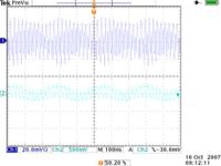 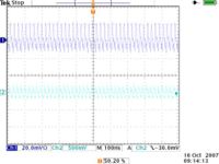 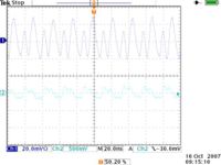
|
| 5.0 | 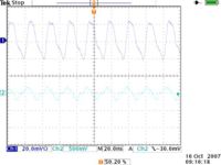
|
| 5.3 | 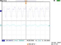
|
| 5.5 | 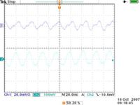
|
| 5.6 | 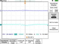
|
| 5.8 | 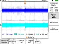
|
- Observations
- The peak-to-peak sense wire maximum noise level of 20 mV converts to a 100 mV peak-to-peak noise level coming out of the amplifier when the board is powered at 5.8 Volts.
Drift chamber High voltage settings
| HV settings | |
| Wire | Volts |
| Sense | 1800 |
| Field | -800 |
| Guard | 800 |
I should have set the Field and Guard wires to 900 volts according to Mac's e-mail reporting his Garfield simulation results. Next time.
Scope pictures triggering on sense wire C2
The scope trigger threshold was set to below -14 mV on Ch 1 based on previous measurements. Sense wire 2 is plugged into Channel 1 on the scope and the preamp output for channel 2 (Pin #2) is connected to channels 2 of the scope.
Scope pictures triggering on preamp output (pin 2)
I found that a trigger threshold of -100 mV on the preamp ouput shown on scope channel #2 discriminated well (but not perfectly:see pictures 2 & 3 below) between noise and pulses consistent with previous ionization events.
