Difference between revisions of "Analysis of evio files"
| Line 25: | Line 25: | ||
Additionally, it is possible that more than one wire will register a hit. We can limit the hits by only accepting the dnhits for the first hit. | Additionally, it is possible that more than one wire will register a hit. We can limit the hits by only accepting the dnhits for the first hit. | ||
| + | |||
[[File:1stHitsLayer1binHits.png]][[File:1stHitsLayer1binHitsWeighted.png]] | [[File:1stHitsLayer1binHits.png]][[File:1stHitsLayer1binHitsWeighted.png]] | ||
Revision as of 18:25, 31 August 2017
Using the evio2root converter
~/src/CLAS/evio2rootDV/bin/evio2root LH2_0Sol_0Tor_11GeV_IsotropicPhi_ShieldOut 105
GEMC 2.4
Restricting hits for Superlayer 1, Layer 1 only
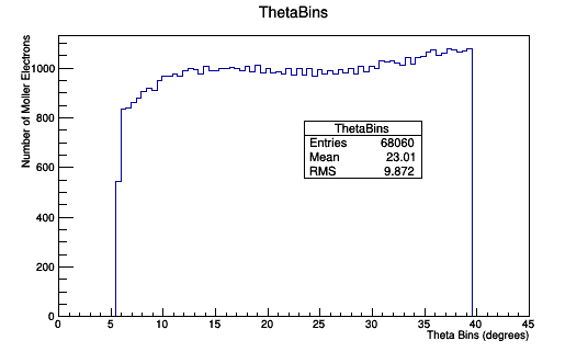
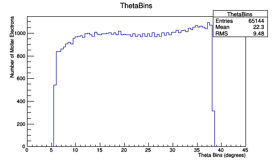
The bumps in what would otherwise be an isotropic distribution of the theta and phi values for particles is caused by two factors.
The foremost factor is that the detector has limits of near the 20degrees in phi as theta reaches 5degrees. Angles outside this limiting factor are provided in the LUND file, but if an interaction where to occur, it would not be in sector 1. These angles would correspond to neighboring sectors.
The second cause is that angles of theta outside the range 5-40 degrees would contribute to wire interactions on the left and right hand sides of the ellipse marked out on the detector plane.
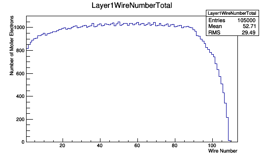
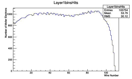
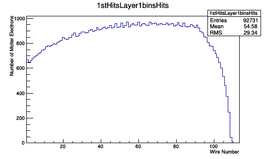
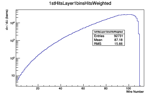
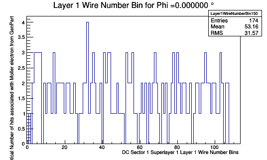
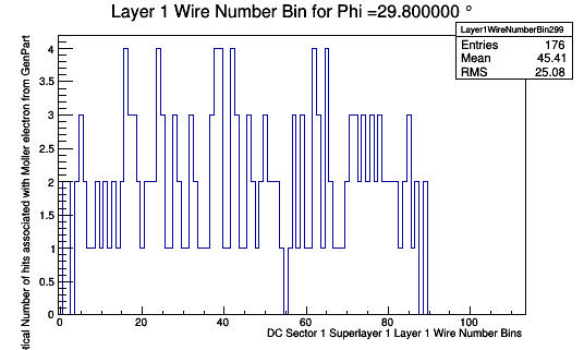
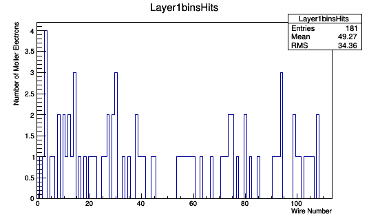
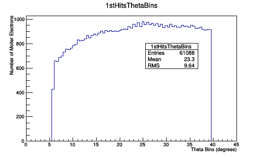
Additionally, it is possible that more than one wire will register a hit. We can limit the hits by only accepting the dnhits for the first hit.
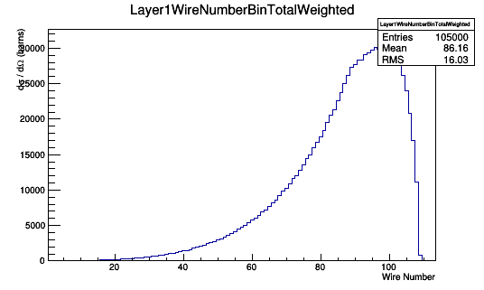
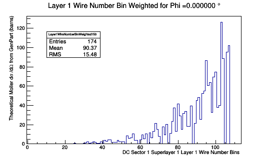
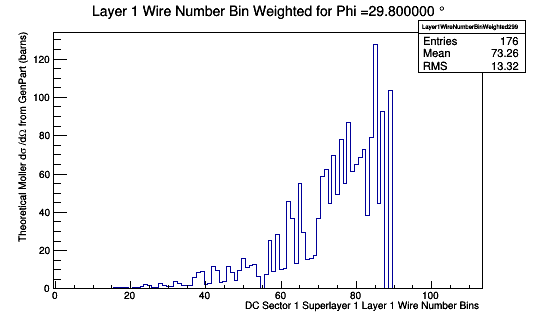
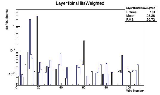
The hits on DC Sector 1 Superlayer 1 Layer 1 have an artificial bump near the middle due to the decreasing wire number as phi (or the parameter of the ellipse) moves away from its semi-major radii with respect to the ellipse of constant theta.
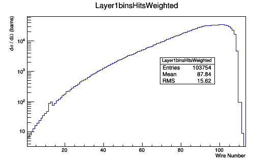
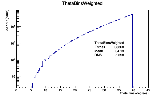
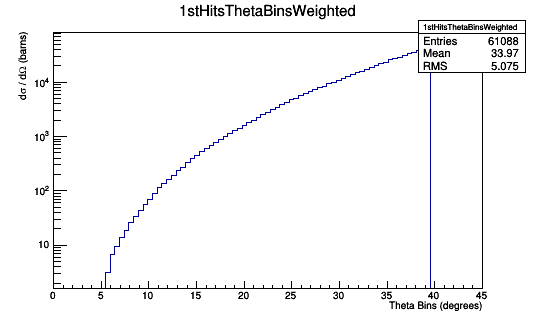
We can run a larger simulation or we can use the wire hit and phi angle to find theta within a certain range. This information can be used to make a plot of number of hits per angle theta bin on which the differential cross section can be overlayed. Theoretically the phi data would be obtained from additional layers in the sector as well as timing data.
Again, restricting hits to only the 1st hits within layer 1
GEMC 3.0
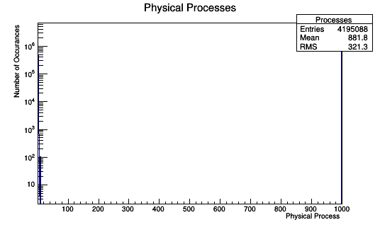
GEMC 3.0 has changed the particle ID for transportation from 99 to 999
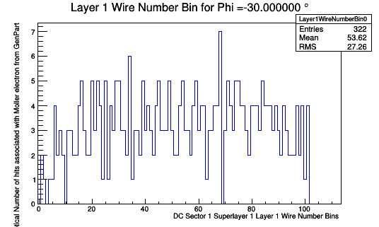
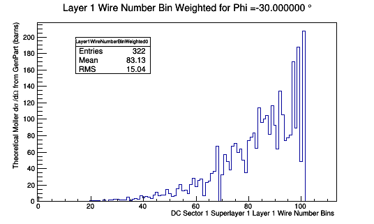
GEMC 3.0 seems to not have as many interactions on layer 1 of section 1 superlayer 1
This lack of interactions translates to angle bins as well
