Difference between revisions of "JB DAQ"
| Line 2: | Line 2: | ||
=AccApp poster= | =AccApp poster= | ||
| + | [[File:AccAppPoster(draft1).pdf]] | ||
=DAQ commands= | =DAQ commands= | ||
Revision as of 21:16, 25 July 2017
Back JB Analysis
AccApp poster
DAQ commands
Source CODA and ROOT
source ~/CODA/2.6.2/setup
source /home/daq/src/root/root-5.34.00/bin/thisroot.csh
Run the bash script titled 'jeff', which takes the run number as an argument. This script will automatically convert the .dat file to a .root file and then open it in root. The script: File:Jeff.txt.
bash jeff 4716
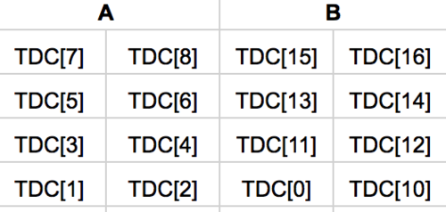
The first index of evt.TDC1190 is the hit #. The second index increases consecutively with TDC channel number, but the index starts from 1, while the TDC channels start at 0.
Common ROOT plot commands for copy-past
First hit minus second hit
R1DC->Draw("(evt.TDC1190[2][16]-evt.TDC1190[1][16])")
Top-Bottom difference
R1DC->Draw("(evt.TDC1190[1][2]-evt.TDC1190[1][3])/10","evt.TDC1190[1][2]!=0 && evt.TDC1190[1][3]!=0 && evt.TDC1190[1][1]!=0")
ToF
For FF config:
FF->Draw("(TDC.TDC1190[1][9]/10+TDC.TDC1190[1][10]/10)/2-TDC.TDC1190[1][25]/10>>ToF(1000,-200,800)","TDC.TDC1190[1][9]!=0 && TDC.TDC1190[1][10]!=0 && TDC.TDC1190[1][25]!=0")
For R1DC config:
R1DC->Draw("0.1*((TDC1190[1][3]+TDC1190[1][4])/2-TDC1190[1][25])>>ToF(1000,-200,800)","TDC1190[1][3]!=0 && TDC1190[1][4]!=0 && TDC1190[1][25]!=0")
TDC Calibration
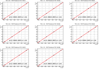
Double pulses separated by 500,600,700, and 800 ns (as measured by an oscilloscope) were used to determine the constant of proportionality between TDC channels and ns. There are 0.1 ns per ch.
Miscellaneous
Pace of signal
The pace of a signal in a 223/U cable is 1.5 ns/ft.
Backwards dead time of digital delay modules
When an input receives 2 or more pulses over a duration less than or equal to (the delay) + (the output pulse width) + (~0-20 ns), only the final pulse received during this duration will appear in the delayed output signal.
solution:
Connect one of the two available the outputs (OUT) to the VETO. This causes the device to reject multiple pulses during the delay duration, ensuring that the delay is constant with respect to the initial pulse.
CAEN N841 discriminator channel multiplicity
The device has an output in the rear labeled which outputs a 50*N mV signal, where N is the number of channels over threshold. This can be used to do coincidence counting such as "three of greater active channels", by feeding the output into a discriminator channel and setting the threshold accordingly.
NIM/ECL translator channel to ROOT channel
e.g. NIM/ECL channel 2A maps to evt.TDC1190[1][3]

