Difference between revisions of "Tamar Thesis EperimentalSetupChapt"
| Line 1: | Line 1: | ||
| − | |||
| − | |||
| − | |||
| − | |||
| − | |||
| − | |||
| − | |||
| − | |||
=Target= | =Target= | ||
Revision as of 06:42, 16 April 2012
Target
Introduction
Polarized targets and polarized beams are an important part of the scattering nuclear and particle physics experiments, which investigate the spin structure in the nucleon. In inclusive scattering experiments using the polarized targets and beams give availability to measure observables with utilizing spin degrees of freedom, like the spin structure of the nucleon, the electromagnetic structure of the nucleon in its ground state and etc. <ref name="Averett1999"> T.D. Averett et al. (1999). "A solid polarized target for high-luminosity experiments". Nucl. Instr. Meth A 427/3, 440-454</ref> The technology producing targets containing polarized nucleons have been developed over the past 50 years. For the experiments using electrons as probes, due to the small cross section of the electromagnetic interactions, one of the requirements for polarized targets are a large thickness and resistance to the electron beam intensity without significant radiation damage. The solid targets for the EG1B experiment were polarized via the Dynamic Nuclear Polarization (DNP) method.
Polarized Target Materials
The main challenge using the polarized solid targets in scattering experiments were the low resistance of the materials to radiation damage. At present, the solid ammonia is the target material with the highest resistance to the radiation damage. Ammonia targets were selected because of their ability to produce high polarization and be resistant to high radiation dose caused by the incident electron beam. Another advantage of ammonia target is a high ratio of free nucleons (~3/18), approximately 16.7 % for and 28.6% for . One disadvantage of choosing ammonia is the polarization background caused by (spin - 1/2), or (spin - 1), which was accounted for by taking data using a solid target <ref name="Keith2003"> Keith, C. D., et al. (2003). A Polarized target for the CLAS detector. NIM, A(501), 327-339. 327-339.</ref> <ref name="Chen2006">Chen, S. (2006). First Measurement of Deeply Virtual Compton Scattering with a Polarized Proton Target. Doctoral dissertation. Florida State University, Tallahasee, FL. </ref>. The main target materials used for the EG1b experiment were frozen ammonia, , for the polarized protons and deuterated ammonia, for the polarized deuterons. In addition to and targets, , liquid and solid were used to estimate the dilution of the data by background noise which can be attributed to the interaction of the incident electron with the Nitrogen or Helium nucleons present in the target cell. This estimate is referred to as a dilution factor <ref name="Keith2003"> Keith, C. D., et al. (2003). A Polarized target for the CLAS detector. NIM, A(501), 327-339. 327-339.</ref> .
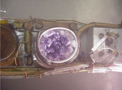
The target materials for EG1B experiment were prepared by slowly freezing the ammonia gas at and after that crushed into small pieces of 1 - 3 mm in diameter at the Polarized Target Lab of the University of Virginia Physics Department. This design of the target helps to cool it effectively via the liquid helium during the experiment and reduce the damage from the radiation heat. After this, free electrons are introduced into the frozen ammonia by irradiating it with an electron beam with a dose of at a temperature near and polarized using DNP method <ref name="CLASNOTE9004">Burkert, V., Mecking, B., Day, D., McCarthy, J., Minehart, R. Polarized Target Experiments Using the CEBAF Large Acceptance Spectrometer. CLAS - Note 90 - 04.</ref>. During the experiment, the polarized target is slowly damaged in the electron beam. This damage can be repaired by warming up the target material to the temperature up to for NH3 and higher for ND3. During the annealing, the free radicals (paramagnetic centers) produced at low temperatures are recombined, decreasing the number of paramagnetic centers. After repeating this process several times, the target materials exhibit significant decrease in the polarization and have to be replaced. The polarized target granules change their color from grey to purple after the radiation damage (Fig TargetPurple).
Dynamic Nuclear Polarization (DNP) is a process in which the polarization of free electrons is transferred to a nucleus<ref name="Chen2006">Chen, S. (2006). First Measurement of Deeply Virtual Compton Scattering with a Polarized Proton Target. Doctoral dissertation. Florida State University, Tallahasee, FL. </ref> . In DNP the target is doped with paramagnetic impurities by chemical doping or by irradiating the target in an electron beam. For low temperatures, on the order of and high magnetic fields on the order of 2.5 , the free electron polarization approaches 100%, on the other hand the protons inside the target are unpolarized. An applied microwave field with a frequency close to the electron spin resonance induces transitions which flip the spin of the electron and, because of the electron-nucleus hyperfine couping, a nearby proton. The relaxation time of the electron is , whereas the relaxation time of the proton in the target is . Due to such a big difference of the relaxation time of the proton and electron, the flipped electron spin rapidly returns to its thermal equilibrium state from where it induces a proton spin-flip again. As a result, the spin polarization is transferred to the protons after some time. The average beam-target polarization product for the EG1b experiment was and for the NH3 and ND3 targets respectively. <ref name="Dharmawardane2006"> Dharmawardane, K.V., et al., (The CLAS Collaboration). (2006). Measurement of the x and -Dependence of the Spin Asymmetry A1 on the Nucleon. Phys. Lett., B(641), 11.</ref>
EG1b Polarized Target System
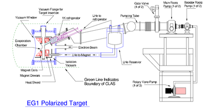
EG1b polarized target system consists the following main components: the superconducting Helmholtz coils to reach 5 T magnetic field, the evaporation refrigerator for target cooling, the microwaves to induce spin flip in the target, NMR system measuring the target polarization and the housing for the solid target.
Target Magnet
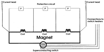
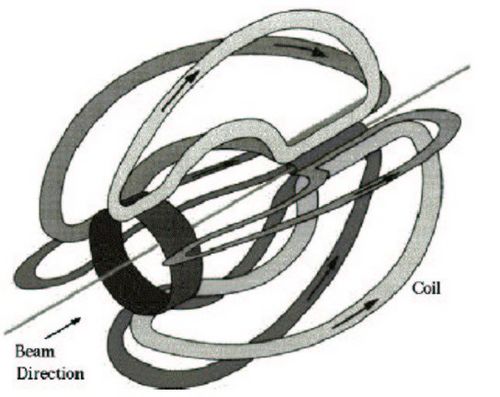
A 5 T magnetic field is established using a pair of superconducting Helmholtz coils made out of Niobium-Titanium mixture with a critical temperature of 9 K. The magnet becomes superconducting below its critical temperature. The resistance of the magnet switch is much higher than the rest of the magnet after warming the switch up above its critical temperature, which induces the current between the magnet and Current leads. This process is called "the magnet energization". After the coils has been energized the switch is turned off, reducing the current flow between the magnet and leads and forcing the current to flow through the coils and switch. After the current in the leads is ramped down, the full current of the magnet is carried by the superconducting Helmholtz coils. The field decay rate during the experiment was 1 part in per hour.
The superconducting coils are oriented such that the magnetic field is parallel to the incident beam direction. The field induces the hyperfine splittings needed to polarize the target material using 140 Ghz RF waves. The uniformity of the field varies less than over a cylindrical volume of 20 mm in diameter and length. This configuration is necessary for DNP. The particles with scattering angles between 0-50 degrees are detected in the CLAS as well as 75-105 degrees. The Helmholtz coils block particles scattering between 50 and 75 degrees. The target magnetic field does not interact with the electron beam, however, it is effective in shielding the drift chambers from low energy Moller electrons. The target field bends the scattered particles in the azimuthal direction and falls rapidly with distance as (). The effect of the magnetic field on the drift chambers is negligible <ref name="Chen2006">Chen, S. (2006). First Measurement of Deeply Virtual Compton Scattering with a Polarized Proton Target. Doctoral dissertation. Florida State University, Tallahasee, FL. </ref> .
The Evaporation Refrigerator
The target material is located at the center of the magnet in a separate chamber, so called banjo. Cooling of the target to approximately 1 K was achieved via a evaporation refrigerator inserted through a 20 cm diameter pumping tube. The pumping tube connects the banjo and the pumping system. The components of the refrigerator are the sintered copper separator pot, two series of heat exchangers and two lines that supply helium to the banjo. The phase separator allows the liquid pass, but blocks the helium vapor. The helium vapor is pumped away to cool the radiation baffles. The liquid in the phase separator is directed to the banjo via one of the two lines and heat exchangers remotely controlled by needle valves. The presence of the liquid helium in the target chamber cools target material effectively.
The Microwave System
For dynamic nuclear polarization process in a magnetic field the ammonia target placed under the microwaves. They are supplied by the Extended Interaction Oscillator (EIO) tube providing power at the anode with a ~ bandwidth tube. The frequency can be adjusted by mechanically changing the size of the resonant cavity. Using the high power voltage supply () the microwave frequency can be finely tuned over a range of . The negative and positive spin states of the nucleon are differed by ~ , because of that target polarization can be changed by varying the microwave frequency. Target spin flipping without changing the magnetic field direction reduces the target contribution to the experimental systematic error.
The microwaves are delivered to the target material using the rectangular gold-plated wave guides outside the cryostat and a tube made out of inside the wave guide system. The tube and the wave guide is connected by a rectangular-circular component. The tube is connected to the rectangular segment of the wave guides suppling microwaves to the desired target cell during the experiment.
The Nuclear Magnetic Resonance System
The polarization of the target material during the experiment was monitored using Nuclear Magnetic Resonance (NMR) techniques. The technique lies in detecting the produced nuclear magnetic transitions. The rate of transitions is related to the population difference of the energy levels giving the information on the original target polarization. The magnetization of the sample, of volume , with spins, each with spin value is
When the external magnetic field is placed perpendicularly under a rotating resonance frequency field with amplitude and frequency of and respectively, the nuclear Zeeman transitions are induced in the target material. The rate of these transitions allows to measure the target polarization. The current in the coil, that surrounds the target generates an oscillating resonance frequency. The absorption or emission of energy by the coil (energy gain or loss in the resonance circuit) indicates the sign of the target polarization.
"A measurement of the ratio of the strengths of the NMR signal with and without RF applied gives the polarization of the target relative to the calculable thermal equilibrium (TE) polarization." The polarization of protons (the spin ) and for deuterons at thermal equilibrium are given as
and
where is the Boltzmann constatnt, - external magnetic field, () - proton (deuteron) magnetic moment and - temperature. During the experiment, the target polarization using NMR was measured via Q-meters of the Liverpool-type. It measures the voltage and related power gain or loss in the coil as a function of the input frequency. The Q-meter circuit is powered by a generator which sweeps the RF frequency through the Larmor frequency of the target. The inductance of the coil changes when the target absorbs or emits energy, producing the impedance change of circuit. The impedance change is related to the circuit voltage output. After accounting for the background measurement of the Q-meter for the input frequency and calibrating the system via the Thermal Equilibrium measurements, the target polarization is extracted.
The Target Chamber
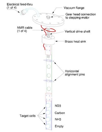
The target chamber is placed at the top of the cryostat. The chamber is filled with the to keep the target material cool. It contains four target cells that are held by the aluminum structure. The cells are made of plastic material (polychlorotrifluoroethylene(PCTFE)) with a wall thickness of , in order to minimize the amount of material other than target. The target cells are in diameter and in length. The PCTFE material was chosen for its high resistance to the radiation damage and for the absence of hydrogen. The aluminum structure is connected to a brass disk minimizing the heat load due to radiation. In order to reduce the thermal conductivity along the target chamber, teflon block was placed between the aluminum structure and the brass disk. The disk itself is connected to the top flange by a threaded stainless steel rod. The stainless steel rod is attached to the stepping motor.
During the run, two of the target cells were filled with and , third cell with a thick graphite disk and the last cell was left empty. The and targets were used for physics measurements, while the carbon and the empty cells for background elimination. The desired target cell can be placed along the beam axis by moving remotely the stepping motor. The NMR coils were wrapped around the outside surface of the cells. The coils, a in diameter tubing, was shaped rectangularly. Only one loop of NMR coils was used for the target, while the target required four loops to measure the polarization. Temperature sensors were located at several places of the target chamber and heater coils were attached below each target cell for annealing.
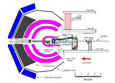
The CEBAF Large Acceptance spectrometer
The Torus Magnet
The CLAS's torus magnet consists of six superconducting coils located around the beam line in a toroidal geometry, producing a magnetic field in the direction when the z-axis of a spherical coordinate system is aligned with the incident beam direction. A sector is defined based on the boundaries of each magnetic coil resulting in a total of six sectors. The maximum current for the CLAS magnet is 2860 Amps corresponding to a total magnetic field in the forward direction of 2.5 T-m and 0.6 T at a polar scattering angle of 90 degrees. The magnet itself is around 5 m in diameter and 5 m in length. The coils of the magnet are cooled by liquid helium circulating through cooling tubes at the magnet's superconducting temperature of 4.5 K <ref name="Prok2004"> Prok, Y. A. (2004). Measurement of The Spin Structure Function of The Proton in The Resonance Region. Doctoral dissertation. University of Virginia, Richmond, VA.</ref>. A charged particle's momentum is determined by the radius of curvature through the magnetic field to a resolution of from 0.5% to 1% <ref name="Fatemi2002">Fatemi, R. H. (2002). The Spin Structure of The Proton in The Resonance Region. Doctoral dissertation. University of Virginia, Sterling, VA. </ref>. In the EG1b experiment, the operated torus values were: 2250, -2250, 1500, -1500 Amps.
Drift Chambers
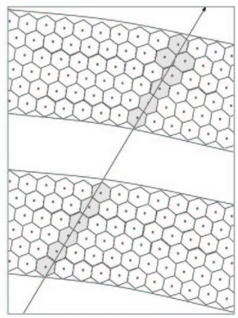
The drift chamber system in the CLAS detector is divided into three regions, each consisting of six separate chambers(sectors). The drift chambers contain three types of wires stretched between the endplates: sense, guard and field. The end plates are attached to the drift chamber so that the angle they form is equal to 60 degrees. Each drift chamber is subdivided into two separate superlayers. Each superlayer has six layers of drift cells. Each drift cell has one sense wire and is surrounded by six field wires forming a hexagonal shape. Each superlayer is surrounded by guard wires at a positive potential to complete the cell symmetry establishing a radial electric field within the drift cells. The sense wire is operated at positive potential and the field wire at negative. In each superlayer the distance between the sense and field wire increases with the radial distance from the target. In R1 the average distance between the sense and field is 0.7 cm, in R2 1.15 cm, and in R3 2.0 cm <ref name="Metayer2000"> Mestayer, M. D., et. al. (2000). The CLAS drift chamber system. NIM, A(449), 81-111.</ref> . The CLAS drift chamber gas is a 90 - 10% mixture of the argon(Ar) and , where Ar has an ionization gain of . Inside the drift chamber, a constant pressure is provided by outflowing the gas. The chamber end plates have a circuit board with a single channel differential pre-amplifier for each sense wire.
The drift chamber system is used to track charged particles. A drift chamber is a particle tracking detector that measures the drift time of liberated electrons in a gas to calculate the spacial position of the ionizing particle.
An electric field in a drift chamber is produced by the anode(sense) and cathode(field) wires. A charged particle traveling through the drift chamber ionizes the gas, freeing electrons that drift to the anodes. After a drift time $(\delta t)$, electrons are collected at the anode(sense wire) generating a pulse for the time measurement. The distance of the traversing particle from the known position of the sense wire can be calculated using the drift time and drift velocity.
Cherenkov detector
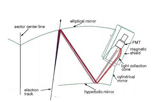
The threshold CLAS Cherenkov detector is used to distinguish electrons from pions. The gas mixture used to fill the Cherenkov counter is perfluorobutane gas at atmospheric pressure. The advantage of perfluorobutane gas is its high index of refraction n=1.00153, which results in a high photon yield. The threshold for Cerenkov radiation can be written as , or for energies , where v is the charged particle velocity, n the index of refraction for the medium, c the speed of light and . In our case . Accordingly, one can calculate the energy threshold for different charged particles; for electrons it is 9 MeV and for pions 2.5 GeV. The Cherenkov detector was designed to maximize the coverage in each of the sectors up to an angle degrees <ref name="Adams2001"> Adams, G., Burkert, V. D., et al. (The CLAS Collaboration). (2001). The CLAS Cherenkov Detector. NIM, A(465), 414-427. </ref> .
Light is collected using a system of mirrors to focus the light onto cones which are connected to the Phillips XP4500B type photomultiplier tubes(PMTs). In the extreme regions of the spectrometer's angular acceptance, the number of detected photoelectrons is too low. Additional photomultiplier tubes were placed in these regions to compensate for the low photoelectron detection efficiency..
Scintillators
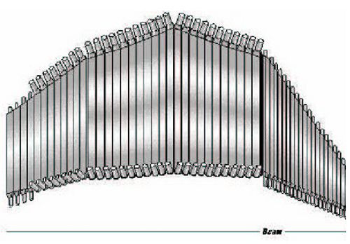
The CLAS is equipped with 288 scintillator counters. The scintillators are used to determine the time of flight for a charged particle and to determine coincidences between particles. The time of flight system has a time resolution at small polar angles of ps and ps at angles above 90 degrees. This time resolution helps discriminate between pions and kaons up to 2 GeV/c. The time of flight system is located between the Cherenkov detectors and the electromagnetic calorimeters. The scintillator paddles are made from BC_408 <ref name="Adams2001"> Adams, G., Burkert, V. D., et al. (The CLAS Collaboration). (2001). The CLAS Cherenkov Detector. NIM, A(465), 414-427. </ref>, are located perpendicular to the average particle trajectory, and have an angular polar coverage of 1.5 degrees each. Each sector of the CLAS detector consists of 48 scintillator paddles with a thickness of 5.08 cm. The length of the scintillators varies from 30 cm to 450 cm and the width is between 15 cm at small polar angles and 22 cm for the large angles <ref name="Smith1999">E.S. Smith, T. Carstens, J. Distelbrink, M. Eckhause, H. Egiyan, L. Elouadrhiri, J. Ficenec, M. Guidal, A.D. Hancock, F.W. Hersman, M. Holtrop, D.A. Jenkins, W. Kim, K. Loukachine, K. MacArthur, C. Marchand, B. Mecking, G. Mutchler, D. Schutt, L.C. Smith, T.P. Smith, S. Taylor, T.Y. Tung, A. Weisenberger, R.E. Welsh (1999). The time-of-flight system for CLAS. NIM, A(432), 265–298. </ref> .
Calorimeter
The CLAS detector contains 8 electromagnetic calorimeter modules. A calorimeter measures the total energy deposited by a particle that enters the detectors acceptance. Calorimeters are sensitive neutral particles with sufficient energy to generate showers and can be used to distinguish between the energy deposited by electrons and hadrons. The CLAS calorimeter has three main functions:
1) detection of electrons at energies above 0.5 GeV;
2) detection of photons with energies higher than 0.2 GeV;
3) detection of neutrons, with discrimination between photon and neutrons using time-of-flight techniques.
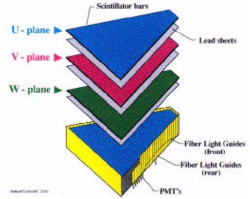
Calorimeter detectors are placed in the forward region of each sector that span polar angles of 10-45 degrees. Two additional calorimeters are located in sectors 1 and 2 that span polar angles of 50 to 70 degrees. The forward calorimeter has a lead/scintillator thickness ratio of 0.2, with 40 cm of scintillators and 8 cm of lead per module. The lead-scintillator sandwich is shaped to form an equilateral triangle in order to match the hexagonal geometry of the CLAS detector. Each scintillator layer contains 36 paddles parallel to one side of the triangle, with this configuration each orientation is rotated by 120 degrees from each other. This gives three views, each containing 13 layers providing stereo information locating the energy deposition. There is a longitudinal sampling of the shower to improve hadron identification. Each set of 13 layers are subdivided into 5 inner layers and 8 outer layers.
Notes
<references/>
