Difference between revisions of "Sadiq Proposal Defense"
| Line 316: | Line 316: | ||
=== Experiment === | === Experiment === | ||
| − | Emittance measurement was carried out on HRRL on July of 2010 under the experimental setup discussed in previous section. | + | Emittance measurement was carried out on HRRL on July of 2010 under the experimental setup discussed in previous section. In this measurement we used analog camera to take images. |
=== Results=== | === Results=== | ||
Revision as of 02:30, 7 September 2011
Abstract
Introduction
We are going to use a High Repetition Rate Linac (HRRL) S-band electron linear accelerator, with frequency of 2856 MHz, to create positrons. HRRL cavity is located at the Beam Lab of the Physics Department, at Idaho State University (ISU).
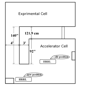
The room HRRL cavity located is divided into two parts by a L-shaped cement wall, we will call them accelerator cell (where cavity located) and experimental cell (where nuclear experiments take palce). Previously cavity was located at the center of the accelerator cell, as shown in figure below. To adapt positron project, it was relocated to new position, as shown in same figure.
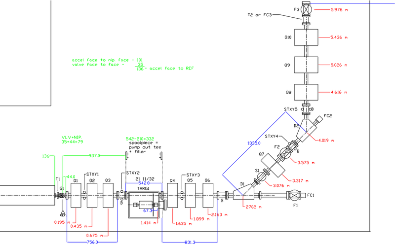
Original HRRL beamline was designed by G. Stancari. Based on this designed, it was improved by Dr. Y. Kim, and was finalized by John Ellis. Design is shown on the following figure.
The beam parts were listed in the following table given by John Ellis.
| Label | Beam Line Element | Z location from Gate Valve center of element | Dimensions of Element |
| T1 | Torroid 1 | -0.05 m | |
| G1 | Fast Gate Valve | 0.000 m | |
| STXY1 | X-Y steerers 1 | want to locate before Q1! | |
| Q1 | First Quad | 0.195 m | (was moved from 0.175 to 0.195) |
| Q2 | Second Quad | 0.435 m | (was moved from 0.425 to 0.435) (24 cm to Q1) |
| Q3 | Third Quad | 0.675 m | (24 cm to Q2) |
| STXY2 | X-Y steerers 2 | ||
| Targ1 | positron production target | 1.175 m | |
| Q4 | Fourth Quad | 1.635 m | (was 1.4 now 1.635) |
| Q5 | Fifth Quad | 1.659 m | was 1.650 drawing has 1.899 we want it at 1.659 (want distance to Q4 to be 24 cm) |
| Q6 | Sixth Quad | 1.683 | was at 1.8 drawing has it at 2.163 we want it at 1.683 (want distance to Q5 to be 24 cm) |
| STXY3 | X-Y steerers 3 | ||
| F1 | OTR Flag | ||
| FC1 | Faraday Cup 1 | ||
| D1 | First Kiwi Dipole | 2.702 m | was 2.525 now it is 2.702 |
| S1 | Energy Slits | 3.076 m | was 2.851 now at 3.076 |
| STXY4 | X-Y steerers 4 | ||
| Q7 | Seventh Quad | 3.317 m | was at 3.026 now at 3.317 |
| F2 | Yag SCREEN | m | attach directly to Dipole D2 and put bellows upstream, drawing has it backwards |
| D2 | Second Kiwi Dipole | 4.019 m | was at 3.617 now at 4.019 |
| Q8 | Eigth Quad | 4.616 m | |
| STXY5 | X-Y steerers 5 | ||
| Q9 | Quad | 5.026 m | |
| Q10 | Quad | 5.436 m | |
| T2 | Torroid 2 | ||
| F3 | Third Flag | 5.976 m | |
| Targ2 | Brehm target ladder | m | |
| HOLE@WALL | 6.412 m |
Electron beam out of cavity will pass through first set of quadruple triplet magnets, which is going to focus electron beam on the positron target. Positrons created in the target will be collected second set of quadruple triplet, then will be bent 45 degree by first dipole magnet. Positron target can be placed in or removed from beam line, so that we run positron or electron dual mode. Accordingly, we change the polarity of the dipoles to run on e-/e+ modes. The The second dipole will bend beam another 45 degree, thus complete total of 90 degree bend. Third set of quadruple triplet will be used create e-/e+ beam profile that sutable for users' specific need.
Motivation
Emittance
What is Emittance
In accelerator physics, Cartesian coordinate system was used to describe motion of the accelerated particles. Usually the z-axis of Cartesian coordinate system is set to be along the electron beam line as longitudinal beam direction. X-axis is set to be horizontal and perpendicular to the longitudinal direction, as one of the transverse beam direction. Y-axis is set to be vertical and perpendicular to the longitudinal direction, as another transverse beam direction.
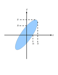
For the convenience of representation, we use to represent our transverse coordinates, while discussing emittance. And we would like to express longitudinal beam direction with . Our transverse beam profile changes along the beam line, it makes is function of , . The angle of a accelerated charge regarding the designed orbit can be defined as:
If we plot vs. , we will get an ellipse. The area of the ellipse is an invariant, which is called Courant-Snyder invariant. The transverse emittance of the beam is defined to be the area of the ellipse, which contains 90% of the particles <ref name="MConte08"> M. Conte and W. W. MacKay, “An Introduction To The Physics Of Particle Accelera tors”, World Scientifc, Singapore, 2008, 2nd Edition, pp. 257-330. </ref>.
Measurement of Emittance with Quad Scanning Method
In quadrupole scan method, a quadrupole and a Yttrium Aluminum Garnet (YAG ) screen was used to measure emittance. Magnetic field strength of the quadrupole was changed in the process and corresponding beam shapes were observed on the screen. Transfer matrix of a quadrupole magnet under thin lens approximation:
Here, is quadrupole strength, is quadrupole magnet thickness, and f is quadrupole focal length. for x-plane, and for y-plane. Transfer matrix of a drift space between quadrupole and screen:
Here, () is the distance from the center of the quadrupole to the screen. Transfer matrix of the scanned region is:
is related with the beam matrix as:
Since:
So, matrix can be written as:
Substituting this give:
Dropping off subscript "rms" on emittance :
Using matrix relations:
Here is . We got:
Recall:
Substituting and reorganizing result in:
Introducing constants ,, and
This will simplify equation to:
It is easy to see that:
By changing quadrupole magnetic field strength , we can change beam sizes on the screen. We make projection to the x, y axes, then fit them with Gaussian fittings to extract rms beam sizes, then plot vs vs . By Fitting a parabola we can find constants ,, and , and get emittances.
First Emittance Measurement Experiment
In July 2010y, Emittance measurement of HRRL was conducted at Beam Lab, at Physics Department of ISU. We installed a YAG crystal on the HRRL beam line to see electron beam. A quadrupole magnet was installed between HRRL gun and the YAG screen. We changed current on the quadrupole to control magnetic field strength of the quadrupole magnet, thus we changed electron beam shape on the YAG screen.
Experimental Setup
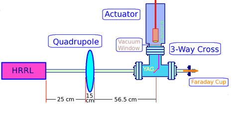
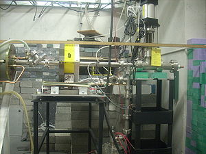
We did quadrupole scan to measure emittance of the electron beam in HRRL. In quadrupole scan method, the strength of the quadrupole magnet was changed by changing the current go through quadrupole coils. The electron beam were coming out of the gun went through quadrupole, then beam would enter a 3-way cross. Two end of the 3-way cross was installed on the beam line. The third end of the 3-way cross was placed upward and there was a actuator installed to it. The YAG crystal was mounted in the actuator, which can put the YAG in the beam line or take it out of the beam line. A camera was placed inside the actuator to look through vacuum a window and to capture the image on the YAG crystal created by electron beam. A Faraday cup was mounted at the end of the beam line to measure the transmission of the charge.
Setup and beam line and are shown in figures 1.2 and 1.3:
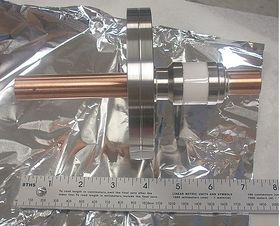
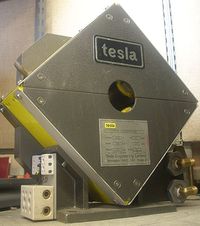
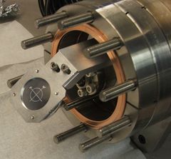
Figures 4, 5, and 6 show Faraday cup, Quadrupole Magnet, and YAG Chrystal used in the test:
Experiment
Emittance measurement was carried out on HRRL on July of 2010 under the experimental setup discussed in previous section. In this measurement we used analog camera to take images.
Results
Future Plan
Energy Scan
Positron Target
Positron Yield
References
<references/>
Go back: Positrons
