Difference between revisions of "TF EIMLab5 Writeup"
Jump to navigation
Jump to search
| Line 2: | Line 2: | ||
=The LC cicuit= | =The LC cicuit= | ||
[[File:TF_EIM_Lab5_LC.png| 200 px]] | [[File:TF_EIM_Lab5_LC.png| 200 px]] | ||
| + | |||
1.) Design a '''parallel''' LC resonant circuit with a resonant frequency between 50-200 kHz. use <math>L</math> = 10 - 100 <math>\mu H</math>, R = 1k <math>\Omega</math> . | 1.) Design a '''parallel''' LC resonant circuit with a resonant frequency between 50-200 kHz. use <math>L</math> = 10 - 100 <math>\mu H</math>, R = 1k <math>\Omega</math> . | ||
| Line 18: | Line 19: | ||
|} | |} | ||
| + | <math>\omega_0 = \frac{1}{\sqrt{L C}} = \frac{1}{33 \mu H \times 1.025 \mu F} = 172 krad/sec</math> | ||
| + | |||
| + | <math>\nu = \frac{\omega_0}{2 \pi} = 27 kHz</math> | ||
2.Construct the LC circuit using a non-polar capacitor | 2.Construct the LC circuit using a non-polar capacitor | ||
Revision as of 15:53, 27 March 2011
LC Resonance circuits
The LC cicuit
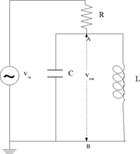
1.) Design a parallel LC resonant circuit with a resonant frequency between 50-200 kHz. use = 10 - 100 , R = 1k .
| Element | Value |
| L | 33 \mu H |
| C | 1.024 \mu F |
| R | 1 k \Omega |
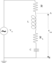
| R_L | 2 k \Omega |
2.Construct the LC circuit using a non-polar capacitor
3. Measure the Gain as a function of frequency. (25 pnts)
4. Compare the measured and theoretical values of the resonance frequency () (10 pnts)
Questions
- What is the bandwidth of the above circuit? (5 pnts)
The RLC cicuit
- Design and construct a series LRC circuit.
- Measure and Graph the Gain as a function of the oscillating input voltage frequency. (25 pnts)
- Measure and Graph the Phase Shift as a function of the oscillating input voltage frequency. (25 pnts)
Questions
- What is the current at resonance? (5 pnts)
- What is the current as ? (5 pnts)

