Difference between revisions of "HRRL 03-14-2011"
| Line 91: | Line 91: | ||
I =165 <math>\mu</math> A | I =165 <math>\mu</math> A | ||
| − | changed from 0<math>\ | + | changed from 0<math>\rightarrow</math> -2 A Output Horizonal moves Beam left and a little up, max trans at zero |
| − | changed 0\ | + | changed 0<math>\rightarrow</math> -0.1 A Down and Left on Output Vertical |
| − | changed 0\ | + | changed 0<math>\rightarrow</math> +0.1 A UP and Right on Output Vertical , current increases slightly |
Max transmission when Output is 0 at Horizontal and +0.1 on Vertical . | Max transmission when Output is 0 at Horizontal and +0.1 on Vertical . | ||
Revision as of 22:08, 14 March 2011
Beam alignment
The goal will be to determine the HRRL steerer and solenoid settings to transport 10 MeV electrons down the zero-line. The desired current is 80 mA peak and 50 nsec wide pulses, ~ 10 Hz repetition rate (or a rate to see OTR images).
Find Best Steering Set
1) The most upstream solenoid is used to adjust the gun emmittance and the downstream solenoid will adjust the beam size. Turn off both solenoids
2) Turn off all the quads.
3) Maximize the transmission along the zero beam line using the front and rear steering coils
4) Turn on the beam downstream solenoid and to adjust the beam spot size. If the beam spot moves on the OTR target, then the beam is not coming out of the HRRL.beam center moves on the screen?
5) Adjust the HRRL steering coils until the beam spot does not move when the downstream solenoid current changes.
6) Repeat step 3 and 4, until beam center does not change by change solenoid strength.
This is the best steering set. Record corresponding current settings.
Quad centering
1) Turn on just one quad at a time. Change quad strength, see if there is steering by the quad.
2) If there is steering by the quad, move the quad. If the steering is vertical (horizontally) move the quad vertically (horizontally). Do it Until beam can not be steered by the quad.
3) Repeat 2 for all the quads.
Beam Line Alignment
1) We moved first dipole to the beam right. Front of moved 6 mm, back moved 12mm.
Out put vertical steering at 0 Amp, beam went of the screen. When current was increased beam spot goes down to the viewer (OTR).
2) We moved a lot back and forth since step 1), we lost track.
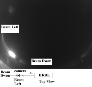
Camera Orientation.
Moving OTR target & FC for Max trans
We turn off the solenoids.
We use the steerers that are closest to the Gun (Input Horizontal/Vertical)
| FC Current | H1 (Input Horizontal) | V1 (Input Vertical) | FC + OTR move |
| mA | A | A | |
| 35 | + 0.0 | +0.3 | 5 mm beam right |
| 60 | +0.2 | -0.1 | 4 mm beam right |
| 7 | +0.3 | -0 | 8 mm beam right |
| 34 | +0.3 | -0 | 4 mm beam left |
| 65 | +.3 | 0 | Moved From OTR beam right 2 mm and rear FC beam left 6 mm (rotation) |
| 66.5 | .2 | 0 | Chad optimized H1 and H2 for maximum current |
| 48 | .2 | 0 | rotated OTR some more, 4 mm , FC was 8 mm beam left of spot it is now 5 mm from spot, should move FC beam left 3 mm, OTR target looks centered now. |
| 51.6 | .2 | .2 | Chad optimized H1 and H2 for maximum current |
| 52 | .2 | .2 | FC was 5mm from the spot now it is 9 mm from the spot. I wonder if there is some relaxation |
| 53 | .3 | .2 | Chad optimized H1 and H2 for maximum current |
Turn on solenoids in series
136 when the solenoids are at 16.2 A.
Now change horizontal and vertical
H1 = -0.5A
V1= +0.4 A
I =165 A
changed from 0 -2 A Output Horizonal moves Beam left and a little up, max trans at zero
changed 0 -0.1 A Down and Left on Output Vertical
changed 0 +0.1 A UP and Right on Output Vertical , current increases slightly
Max transmission when Output is 0 at Horizontal and +0.1 on Vertical .
Take OTR picture zero point is now.
Changing solenoids independently drops transmission. Both solenoids are at Max current 16.2A nearest gun, 15.8 Amp on the output Solenoid.
