Difference between revisions of "Instruments and Equipments"
| Line 217: | Line 217: | ||
|}<br> | |}<br> | ||
| + | |||
| + | === Vertical Scan === | ||
| + | |||
| + | Gap width <math> \aprox </math>5cm. | ||
==== Power on X = 124.5, Y = 150 ==== | ==== Power on X = 124.5, Y = 150 ==== | ||
Revision as of 03:38, 17 January 2011
Magnets
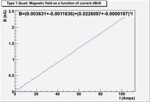
Type 1 Quad (also Quad2A )
Measurement on Magnetic field as a function of current dB/dI
Data File: File:Magnet T1Quad data.txt
ROOTSYS file to analyze this data, create figure and fit: File:Magnet T1Quad cpp.C
Figure and Fit:
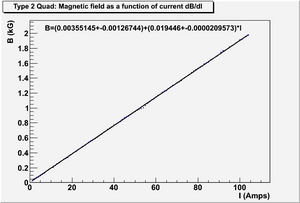
Type 2 Quad (also Quad2T )
Measurement on Magnetic field as a function of current dB/dI
Data File: File:Magnet T2Quad data.txt
ROOTSYS file to analyze this data, create figure and fit: File:Magnet T2Quad cpp.C
Figure and Fit:
Magnet Mappings
Dr. Chouffani's Note
Kiwi Dipole Mappings
File:Kiwi Dipole Magnet Mappings.pdf
Tag Number: 079220
Bending magnet that was to be used with LCS (compact magnets) The horizontal and vertical tranlator have a range for 150 mm i.e. 15 cm.
Power on I = 20.4 A
| x (mm) | y (mm) | B (kG) | |
| 127 | 0 | ||
| 127 | 10 | -0.106 | |
| 127 | 20 | -0.169 | |
| 127 | 30 | -0.2729 | |
| 127 | 40 | -0.448 | |
| 127 | 50 | -0.728 | |
| 127 | 60 | -0.97 | |
| 127 | 70 | -1.025 | |
| 127 | 80 | -1.029 | |
| 127 | 90 | -1.03 | |
| 127 | 100 | -1.029 | |
| 127 | 110 | -1.028 | |
| 127 | 120 | -1.028 | |
| 127 | 130 | -1.028 | |
| 127 | 140 | -1.028 | |
| 127 | 150 | -1.028 | |
| y = 150 mm is roughly center of the bend. | |||
| 127 | 150 | -1.028 | |
| 127 | 140 | -1.031 | |
| 127 | 130 | -1.0342 | |
| 127 | 120 | -1.036 | |
| 127 | 110 | -1.036 | |
| 127 | 100 | -1.036 | |
| 127 | 90 | -1.036 | |
| 127 | 80 | -1.0355 | |
| 127 | 70 | -1.03 | |
| 127 | 60 | -0.977 | |
| 127 | 50 | -0.7354 | |
| 127 | 40 | -0.4527 | |
| 127 | 30 | -0.275 | |
| 127 | 20 | -0.17 | |
| 127 | 10 | -0.1066 | |
| 127 | 0 | -0.0673 | |
| Again | |||
| x (mm) | y (mm) | B (kG) | |
| 127 | 0 | ||
| 127 | 10 | -0.1062 | |
| 127 | 20 | -0.1699 | |
| 127 | 30 | -0.2738 | |
| 127 | 40 | -0.449 | |
| 127 | 50 | -0.7283 | edge of poles 100 px |
| 127 | 60 | -0.9712 | |
| 127 | 70 | -1.0253 | |
| 127 | 80 | -1.03 | |
| 127 | 90 | -1.03 | |
| 127 | 100 | -1.0298 | |
| 127 | 110 | -1.028 | |
| 127 | 120 | -1.0285 | |
| 127 | 130 | -1.0286 | |
| 127 | 140 | -1.0282 | |
| 127 | 150 | -1.0278 |
| x (mm) | y (mm) | I | B (kG) | |
| 127 | 150 | 20.1 | -1.0279 | |
| 127 | 150 | 30.1 | -1.53 | |
| 127 | 150 | 25.1 | -1.2916 | |
| 127 | 150 | 20.1 | -1.0359 | |
| 127 | 150 | 15 | -0.781 | |
| 127 | 150 | 10 | -0.534 | |
| 127 | 150 | 5 | -0.277 | |
| 127 | 150 | 0 | -0.017 | |
| Again | ||||
| 127 | 150 | 0 | -0.01726 | |
| 127 | 150 | 5 | -0.266 | |
| 127 | 150 | 10 | -0.518 | |
| 127 | 150 | 15 | -0.7713 | |
| 127 | 150 | 20 | -1.02 | |
| 127 | 150 | 25 | -1.272 | |
| 127 | 150 | 30 | -1.52 |
Power on I = 20 A
| x (mm) | y (mm) | B (kG) | |
| 135 | 150 | -1.0369 | |
| 132 | 150 | -1.0379 | |
| 129 | 150 | -1.0382 | |
| 126 | 150 | -1.0384 | |
| 123 | 150 | -1.0385 | |
| 120 | 150 | -1.0386 | |
| 118 | 150 | -1.0387 | |
| 116 | 150 | -1.0388 | |
| 114 | 150 | -1.039 |
Vertical Scan
Gap width 5cm.
Power on X = 124.5, Y = 150
| x (mm) | y (mm) | I (A) | B (kG) | |
| 124.5 | 150 | 20 | -1.0388 | |
| 124.5 | 150 | 25.1 | -1.2916 | |
| 124.5 | 150 | 20.0 | -1.0359 | |
| 124.5 | 150 | 15 | -0.781 | |
| 124.5 | 150 | 10 | -0.534 | |
| 124.5 | 150 | 5 | -0.277 | |
| 124.5 | 150 | 0 | -0.017 |
| x (mm) | y (mm) | I (A) | B (kG) | |
| 124.5 | 150 | 0 | -0.01726 | |
| 124.5 | 150 | 5 | -0.266 | |
| 124.5 | 150 | 10 | -0.518 | |
| 124.5 | 150 | 15 | -0.7713 | |
| 124.5 | 150 | 20 | -1.02 | |
| 124.5 | 150 | 25 | -1.272 | |
| 124.5 | 150 | 30 | -1.52 |
| x (mm) | y (mm) | I (A) | B (kG) | |
| 124.5 | 150 | 0 | -0.0123 | |
| 124.5 | 150 | 5 | -0.2676 | |
| 124.5 | 150 | 10 | -0.516 | |
| 124.5 | 150 | 15 | -0.771 | |
| 124.5 | 150 | 20 | -1.028 | |
| 124.5 | 150 | 25 | -1.2735 | |
| 124.5 | 150 | 30 | -1.5217 |
| x (mm) | y (mm) | I (A) | B (kG) | |
| 124.5 | 150 | 30 | -1.5218 | |
| 124.5 | 150 | 25 | -1.287 | |
| 124.5 | 150 | 20 | -1.037 | |
| 124.5 | 150 | 15 | -0.7855 | |
| 124.5 | 150 | 10 | -0.5313 | |
| 124.5 | 150 | 5 | -0.2747 | |
| 124.5 | 150 | 0 | -0.0164 |
| x (mm) | y (mm) | B (kG) | |
| 124.5 | 140 | -1.04 | |
| 124.5 | 130 | -1.04 | |
| 124.5 | 120 | -1.0409 | |
| 124.5 | 110 | -1.041 | |
| 124.5 | 100 | -1.0411 | |
| 124.5 | 90 | -1.041 | |
| 124.5 | 80 | -1.0408 | |
| 124.5 | 70 | -1.355 | |
| 124.5 | 60 | -0.9799 | |
| 124.5 | 50 | -0.74 | |
| 124.5 | 40 | -0.457 | |
| 124.5 | 30 | -0.2776 | |
| 124.5 | 20 | -0.1718 | |
| 124.5 | 0 | -0.0684 |
Tag Number: 42125
| x (mm) | y (mm) | I (A) | B (kG) | |
| 0 | 0 | Power off | ||
| 0 | 0 | 20 | ||
| 111.75 | 0 | 20 |
| x (mm) | y (mm) | I (A) | B (kG) |
| 111.75 | 10 | 20 | 0.0637 |
| 111.75 | 20 | 20 | 0.102 |
| 111.75 | 30 | 20 | 0.1675 |
| 111.75 | 40 | 20 | 0.2774 |
| 111.75 | 50 | 20 | 0.4654 |
| 111.75 | 60 | 20 | 0.756 |
| 111.75 | 70 | 20 | 0.9898 |
| 111.75 | 80 | 20 | 1.0312 |
| 111.75 | 90 | 20 | 1.0358 |
| 111.75 | 100 | 20 | 1.0362 |
| 111.75 | 110 | 20 | 1.0363 |
| 111.75 | 120 | 20 | 1.0363 |
| 111.75 | 130 | 20 | 1.0362 |
| 111.75 | 140 | 20 | 1.036 |
| 111.75 | 150 | 20 | 1.036 |
| x (mm) | y (mm) | I (A) | B (kG) |
| 111.75 | 0 | 20 | 0.0402 |
| 111.75 | 10 | 20 | 0.0635 |
| 111.75 | 20 | 20 | 0.1022 |
| 111.75 | 30 | 20 | 0.1674 |
| 111.75 | 40 | 20 | 0.2773 |
| 111.75 | 50 | 20 | 0.4652 |
| 111.75 | 60 | 20 | 0.755 |
| 111.75 | 70 | 20 | 0.9828 |
| 111.75 | 80 | 20 | 1.0312 |
| 111.75 | 90 | 20 | 1.0358 |
| 111.75 | 100 | 20 | 1.0362 |
| 111.75 | 110 | 20 | 1.0362 |
| 111.75 | 120 | 20 | 1.03625 |
| 111.75 | 130 | 20 | 1.0362 |
| 111.75 | 140 | 20 | 1.036 |
| 111.75 | 150 | 20 | 1.036 |
| x (mm) | y (mm) | I (A) | B (kG) |
| 111.75 | 150 | 0 | 0.0076 |
| 111.75 | 150 | 5 | 0.263 |
| 111.75 | 150 | 10 | 0.52 |
| 111.75 | 150 | 15 | 0.7754 |
| 111.75 | 150 | 20 | 1.0313 |
| 111.75 | 150 | 25 | 1.2869 |
| 111.75 | 150 | 30 | 1.5389 |
| 111.75 | 150 | 30 | 1.5389 |
| 111.75 | 150 | 25 | 1.3 |
| 111.75 | 150 | 20 | 1.0484 |
| 111.75 | 150 | 15 | 0.7945 |
| 111.75 | 150 | 10 | 0.534 |
| 111.75 | 150 | 5 | 0.276 |
| 111.75 | 150 | 0 | 0.01386 |
| x (mm) | y (mm) | I (A) | B (kG) |
| 123.25 | 150 | 20 | 1.0339 |
| 120.25.25 | 150 | 20 | 1.0338 |
| 117.25 | 150 | 20 | 1.034 |
| 114.25 | 150 | 20 | 1.034 |
| 111.25 | 150 | 20 | 1.0342 |
| 111.25 | 150 | 20 | 1.0343 |
| 108.25 | 150 | 20 | 1.0342 |
| 105.25 | 150 | 20 | 1.0343 |
| 102.25 | 150 | 20 | 1.0344 |
| 99.25 | 150 | 20 | 1.03435 |
| x (mm) | y (mm) | I (A) | B (kG) |
| 111.25 | 150 | 20 | 1.0339 |
| 111.25 | 0 | 20 | 0.04 |
| 111.25 | 10 | 20 | 0.0633 |
| 111.25 | 20 | 20 | 0.102 |
| 111.25 | 30 | 20 | 0.1671 |
| 111.25 | 40 | 20 | 0.2767 |
| 111.25 | 50 | 20 | 0.4643 |
| 111.25 | 60 | 20 | 0.7544 |
| 111.25 | 70 | 20 | 0.9818 |
| 111.25 | 80 | 20 | 1.0295 |
| 111.25 | 90 | 20 | 1.034 |
| 111.25 | 100 | 20 | 1.0344 |
| 111.25 | 110 | 20 | 1.0345 |
| 111.25 | 120 | 20 | 1.0345 |
| 111.25 | 130 | 20 | 1.0345 |
| 111.25 | 140 | 20 | 4.0343 |
| 111.25 | 150 | 20 | 10.342 |
| x (mm) | y (mm) | I (A) | B (kG) |
| 111.25 | 0 | 20 | 0.04 |
| 111.25 | 10 | 20 | 0.0632 |
| 111.25 | 20 | 20 | 0.1018 |
| 111.25 | 30 | 20 | 0.1669 |
| 111.25 | 40 | 20 | 0.2767 |
| 111.25 | 50 | 20 | 0.4639 |
| 111.25 | 60 | 20 | 0.754 |
| 111.25 | 70 | 20 | 0.9816 |
| 111.25 | 80 | 20 | 1.0294 |
| 111.25 | 90 | 20 | 1.034 |
| 111.25 | 100 | 20 | 1.0344 |
| 111.25 | 110 | 20 | 1.0344 |
| 111.25 | 120 | 20 | 1.0344 |
| 111.25 | 130 | 20 | 1.0343 |
| 111.25 | 140 | 20 | 4.0342 |
| 111.25 | 150 | 20 | 10.342 |
| x (mm) | y (mm) | I (A) | B (kG) |
| 111.25 | 43 mm | 0 | |
| 111.25 | 43 mm | 5 | 0.0822 |
| 111.25 | 43 mm | 10 | 0.1615 |
| 111.25 | 43 mm | 15 | 0.242 |
| 111.25 | 43 mm | 20 | 0.3227 |
| 111.25 | 43 mm | 25 | 0.4014 |
| 111.25 | 43 mm | 30 | 0.4793 |
| 111.25 | 43 mm | 0 | |
| 111.25 | 43 mm | 5 | 0.08 |
| 111.25 | 43 mm | 10 | 0.1613 |
| 111.25 | 43 mm | 15 | 0.242 |
| 111.25 | 43 mm | 20 | 0.3215 |
| 111.25 | 43 mm | 25 | 0.4 |
| 111.25 | 43 mm | 30 | 0.4783 |
Power supplies
ZUP
User manuals: File:Zup-user-manual.pdf
Other documents:
GENESYS
File:GenesysTM 750W-1500W-manual.pdf
Mapping Quadruple Megenets
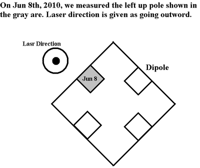
2010-Jun-08 (void)
The magnet type: TYPE 2 Quadrupole.
Serial number of the Quad: 09
Insert serial number of Quad to uniquely identify which type 2 was mapped
| 1st Measurement | 1st Measurement | 2nd Measurement | 2nd Measurement | 5th Measurement | 5th Measurement | 6th Measurement | 6th Measurement | |||
| Current (Amps) | Field (Gauss) | Current (Amps) | Field (Gauss) | Current (Amps) | Field (Gauss) | Current (Amps) | Field (Gauss) | |||
| -5.1 | -101.78 | PS off | -6.565 | |||||||
| 0 | -6.045 | 0 | -2.048 | 0 | -6.126 | |||||
| -2.8 | -59.82 | -2.9 | 60.73 | -2.9 | -52.57 | -2.9 | -58.57 | |||
| -3.6 | -72.93 | -3.7 | 74.81 | -3.7 | -67.16 | -3.7 | -71.83 | |||
| -5.15 | -99.285 | -5.2 | 101.41 | -5.2 | -93.89 | -5.2 | -98.58 | |||
| -7.4 | -139.77 | -7.4 | -142.27 | -7.4 | -135.07 | -7.4 | -138.62 | |||
| -9.6 | -180.93 | -9.6 | -183.55 | -9.6 | -176.37 | -9.6 | -179.19 | |||
| -12.6 | -237.04 | -12.6 | -239.73 | -12.6 | -231.62 | -12.6 | -233.47 | |||
| -15.6 | -293.36 | -15.6 | -294.56 | -15.6 | -286.83 | -15.6 | -287.94 | |||
| -18.5 | -353.28 | -18.5 | -350.66 | -18.55 | -342.02 | -18.6 | -342.46 | |||
| -20.8 | -392.67 | -20.8 | -392.62 | -20.8 | -383.54 | -20.8 | -383.65 | |||
| 0 | -8.94 | 0 | -7.18 | 0 | -8.22 | |||||
| PS off | -8.18 | PS off | -6.45 |
| 3rd Measurement | 3rd Measurement | 4th Measurement | 4th Measurement | 7th Measurement | 7th Measurement | 8th Measurement | 8th Measurement | |||
| Current (Amps) | Field (Gauss) | Current (Amps) | Field (Gauss) | Current (Amps) | Field (Gauss) | Current (Amps) | Field (Gauss) | |||
| PS off | -8.22 | PS off | -7.47 | |||||||
| 0 | -8.76 | 0 | -6.8 | 0 | 0.389 | |||||
| 2.9 | 48 | 2.9 | 54.03 | 2.9 | 46.72 | 2.9 | 52.69 | |||
| 3.65 | 62.43 | 3.65 | 67.55 | 3.65 | 61.40 | 3.6 | 66.39 | |||
| 5.1 | 84.45 | 5.1 | 94.78 | 5.1 | 87.85 | 5.1 | 92.51 | |||
| 7.35 | 131.09 | 7.35 | 135.43 | 7.35 | 128.85 | 7.35 | 132.43 | |||
| 9.6 | 172 | 9.6 | 175.64 | 9.6 | 169.97 | 9.6 | 172.44 | |||
| 12.6 | 228 | 12.6 | 230.8 | 12.6 | 224.75 | 12.6 | 226.44 | |||
| 15.5 | 284.6 | 15.5 | 15.5 | 280.46 | 15.5 | 280.55 | ||||
| 18.5 | 341.5 | 18.5 | 241.6 | 18.5 | 334.67 | 18.5 | 334.89 | |||
| 20.75 | 384.2 | 20.75 | 385 | 20.75 | 376.07 | 20.75 | 375.93 | |||
| 0 | 1.586 | 0 | 2.78 | 0 | 1.601 | 0 | 1.67 | |||
| PS off | 0.851 | PS off | 0.93 |
Dr. Khalid Chouffani said we there were some other sources around magnet, so we don't use the data on 2010-Jun-08.
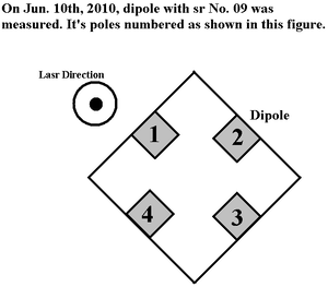
2010-Jun-10
The magnet type: TYPE 2 Quadrupole.
Serial number of the Quad: 09
Pole #4
| 1st Measurement | 1st Measurement | 2nd Measurement | 2nd Measurement | 3rd Measurement | 3rd Measurement | 4th Measurement | 4th Measurement | ||
| Current (Amps) | Field (Gauss) | Current (Amps) | Field (Gauss) | Current (Amps) | Field (Gauss) | Current (Amps) | Field (Gauss) | ||
| PS off | +0.026 | PS off | 7.83 | ||||||
| -0 | 0.716 | -0 | 8.13 | 0 | 8.27 | 0 | -0.6 | ||
| -2.9 | 52.5 | -2.9 | 58.16 | 2.9 | -46.02 | 2.9 | -50.54 | ||
| -5.9 | 106.04 | -5.9 | 109.66 | 5.9 | -99 | 5.9 | -102.36 | ||
| -8.9 | 159.5 | -8.9 | 161.95 | 8.9 | -152.09 | 8.9 | -154.41 | ||
| -12.6 | 226.47 | -12.6 | 227.8 | 12.6 | -218.7 | 12.6 | -220.05 | ||
| -15.55 | 280.17 | -15.55 | 280.8 | 15.55 | -272.03 | 15.55 | -272.65 | ||
| -17.8 | 320.6 | -17.8 | 320.75 | 17.8 | -311.9 | 17.8 | 312.2 | ||
| -20.0 | 360.86 | -20.0 | 361.66 | 20.0 | -351.9 | 20.0 | 351.88 | ||
| -0 | 8.13 | -0 | 8.63 | 0 | -0.6 | 0 | -1 | ||
| PS off | -0.3 |
Pole #1
| 1st Measurement | 1st Measurement | 2nd Measurement | 2nd Measurement | 3rd Measurement | 3rd Measurement | 4th Measurement | 4th Measurement | ||
| Current (Amps) | Field (Gauss) | Current (Amps) | Field (Gauss) | Current (Amps) | Field (Gauss) | Current (Amps) | Field (Gauss) | ||
| -0 | -9.35 | -0 | -9.24 | 0 | -7.67 | 0 | 1.72 | ||
| -3 | -59.35 | -3 | -59.4 | 3 | 44.96 | 3 | 52.13 | ||
| -6.1 | -111.75 | -6.1 | -111.73 | 6.1 | 99.1 | 6.1 | 104.41 | ||
| -9.1 | -164.5 | -9.1 | -164.42 | 9.15 | 153.12 | 9.15 | 156.95 | ||
| -12.2 | -217.83 | -12.2 | -217.75 | 12.2 | 207.12 | 12.2 | 209.8 | ||
| -15.3 | -271.18 | -15.3 | -271.13 | 15.3 | 261.1 | 15.3 | 262.8 | ||
| -18.35 | -326.38 | -18.35 | -324.71 | 18.4 | 315.36 | 18.4 | 316.4 | ||
| -20.0 | -351.7 | -19.9 | -352.33 | 19.9 | 342.5 | 19.9 | 343.06 | ||
| -0 | -9.24 | -0 | -9.03 | 0 | 1.73 | 0 | 1.77 | ||
Pole #2
| 1st Measurement | 1st Measurement | 2nd Measurement | 2nd Measurement | 3rd Measurement | 3rd Measurement | 4th Measurement | 4th Measurement | ||
| Current (Amps) | Field (Gauss) | Current (Amps) | Field (Gauss) | Current (Amps) | Field (Gauss) | Current (Amps) | Field (Gauss) | ||
| 0 | -0.83 | 0 | -0.86 | -0 | 6.45 | -0 | 9.08 | ||
| 3 | -52.86 | 3 | -52.94 | -3 | 58.6 | -3 | 61.08 | ||
| 6.1 | -106.8 | 6.1 | -106.9 | -6.1 | 112.97 | -6.1 | 115.1 | ||
| 9.2 | -160.96 | 9.2 | -161.06 | -9.2 | 167.96 | -9.2 | 169.46 | ||
| 12.3 | -215.64 | 12.3 | -215.72 | -12.3 | 223.5 | -12.3 | 224.3 | ||
| 15.4 | -270.25 | 15.4 | -270.36 | -15.4 | 279.26 | -15.4 | 279.27 | ||
| 18.5 | -325.9 | 18.5 | -325.16 | -18.5 | 335.15 | -18.5 | 334.8 | ||
| 20.0 | -352.44 | 20 | -352.47 | -20 | 362.97 | -20.05 | 363.43 | ||
| 0 | -0.88 | 0 | -1.377 | -0 | 9. | -0 | 9.16 | ||
Pole #3
| 1st Measurement | 1st Measurement | 2nd Measurement | 2nd Measurement | 3rd Measurement | 3rd Measurement | 4th Measurement | 4th Measurement | ||
| Current (Amps) | Field (Gauss) | Current (Amps) | Field (Gauss) | Current (Amps) | Field (Gauss) | Current (Amps) | Field (Gauss) | ||
| PS off | -6.3 | ||||||||
| -0 | -7.2 | -0 | -7.5 | 0 | 3.53 | 0 | 3.12 | ||
| -3.05 | -58.4 | -3.05 | -58.64 | 3 | 52.6 | 3 | 54.73 | ||
| -6.2 | -111.68 | -6.2 | -111.9 | 6.15 | 106.25 | 6.1 | 108.05 | ||
| -9.25 | -165.25 | -9.25 | -167.28 | 9.25 | 160.22 | 9.25 | 161.51 | ||
| -12.35 | -219.35 | -12.35 | -219.56 | 12.35 | 215.43 | 12.4 | 215.3 | ||
| -15.55 | -273.47 | -15.55 | -273.52 | 15.5 | 269 | 15.55 | 270 | ||
| -18.6 | -327.8 | -18.6 | -327.73 | 18.6 | 232.7 (check) | 18.6 | 325.1 | ||
| -20.1 | -355.72 | -20.1 | -354.85 | 20.1 | 350.93 | 20.15 | 350.5 | ||
| -0 | -7.5 | -0 | -7.28 | 0 | 3.12 | ||||
Flag
Light on the flag
5 V. Brown and orange wires are for the light.
Camera on the Flag
12 V. Black and white wires are for the camera.
Air gate on the Flag
Open at 17 V, close at 7 V. Red and green wires are for the air gate.
Red = +17 V and Green = ground?
Green is connected to negative.
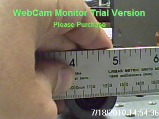
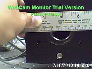
Current Camera dimension
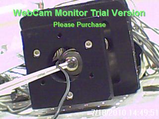
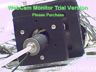
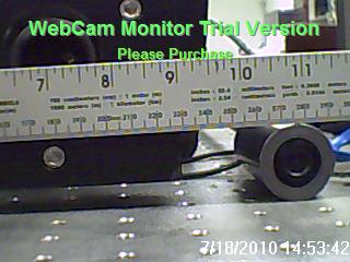
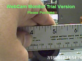
Current camera in the flag is placed in the cylindrical tube of the flag. Camera can be slided into the flag, and the distance can be controlled. Camera itself is cylindrical shaped, and placed into a cylindrical tube. The tube has 2 cm of inner diameter and 3 cm of outer diameter. Camera has 2 cm diameter.
JAI Camera
software download
http://www.jai.com/EN/CameraSolutions/Download/Pages/JAI_SDK_and_control_tool.aspx
http://www.1stvision.com/cameras/gige-camera-accessories.html
Cable
Part Number: CB-AVT-I/O-xx
Color Coding
PIN#               Color
1..................Brown
2..................Red
3..................Orange
4..................Yellow
5..................Green
6..................Blue
7..................Violet
8..................Gray
9..................White
10.................Pink
11.................Light Green
12.................Black
Shell..............Drain Wire
Rev.3 4/6/10
Hardware Triggering The Camera
Pulse signal need to be send to "TTL IN 1" (pin# 6, Blue), "TTL IN 2" (pin# 7, Violet) or "TTL IN 3" (pin# 10, Pink).
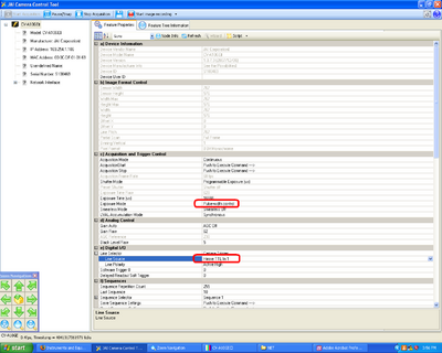
At JAI Camera Control Tool, set
c) Acquisition and Trigger COntrol:
"exposure mode" -> "Pulse-width control"
e) Digital I/O:
"Line Selector" -> "Line Source" -> "Hirose TTL In 1" (or In 2 and In3, depending on wich TTL In signal is being sended.)
JAI Camera Control
Controlling the Camera with Labview
169.254.1.106
134.50.203.196
Third Party Software for JAI GigE Vision Cameras:
National Instruments - JAI GigE Vision cameras are compatible with NI's Vision Acquisition Software and related image processing modules, including integration with the LabVIEW graphical programming environment.
NI Machine Vision Software
National Instruments has been a leader in machine vision and image processing for nearly a decade and currently supports thousands of different cameras. To acquire, display, save, and monitor images from cameras, use NI Vision Acquisition software, which is included with all NI frame grabbers and sold separately for FireWire and Gigabit Ethernet image acquisition. To process images, NI Vision software comes in two different packages: the Vision Development Module and NI Vision Builder for Automated Inspection (AI). The Vision Development Module is a collection of hundreds of vision functions for programmers using NI LabVIEW, NI LabWindows/CVI, C/C++ or Visual Basic. Vision Builder AI is an interactive software environment for configuring, benchmarking and deploying machine vision applications without programming. Both software packages work with all NI Vision frame grabbers and the NI Compact Vision System.
Labview error message
It looks like the NI software from 2009 was downloaded. There are 2 more recent versions. Perhaps if we use the latest software the error message will go away?
http://joule.ni.com/nidu/cds/view/p/id/2137/lang/en
Found the following link below which has a Camera File for use with NI-IMAQ 3.1 or later Created by: NI Certified Created on: 4/28/2005
http://sine.ni.com/apps/utf8/nipc.product?pid=6902
JAI says that I should upgrade the GiGE firmware. The company does this so I need to send in the camera.
FLEA2 camera
FLEA2 camera uses firewire output which only travel about 15 ft. You can either put the computer in teh same room as the acceleerator and risk rad damage or buy a set of LDF repeater hubs to extend the distance up to 100 m.
FL2-14S3C-C = FLEA2 1394b camera 1/2" CCD C-Mount , $995, File:FLEA2 Datasheet.pdf
FWB-LDR-CAT5 = LDR 800 Mb/s repeater, comes with 2, one for the camera end and one for the computer end, $295 File:LDR FirewireRepeater Datasheet.pdf
DEVKIT = camera software drivers, kit with cables to power and trigger the camera and a PCI card for the PC, $100
External power supply for the camera: http://www.ptgrey.com/products/accessories/misc/ACC-01-9002.pdf
Camera Telescope
OTR with Al
File:M.Castellan NIM A357 1995 pp231.pdf
Preferred camera:
http://www.ptgrey.com/products/flea2/flea2.pdf
saves images in ASCI format
6 Way Cross
Diameter of the window: 3 inches.
Distance from the 6-way-cross to the floor (Not from the center, but from the bottom window to the floor.): inches = 94.615 cm.
The distance from the Center of HRRL beam pipe to the floor is: 106.3 cm
Optics for Emittance Measurement in Feb 2010
Iris
Lens
Diameter: 5 cm.
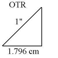
We can use 3 lens system to hold image directly at the sensing area of the CCD camera. Sensing are of the JAI CCD camera is 6.49(h) x 4.83 (v) mm and field of view of our interest has a diameter of 1 inch.
Since OTR is placed 45 degree to vertical plane, one of the dimension of the OTR image actually is 1.796 cm. If we put this to vertical dimension of the camera and put the other dimension of image on the horizontal dimension of the camera, the magnifications we need to hold the view of our interest on the 50% of the sensing area of the camera will be:
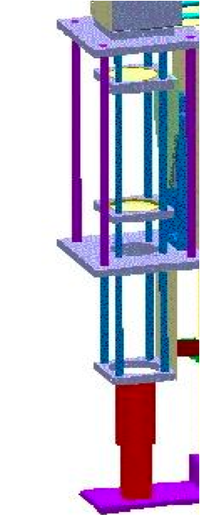
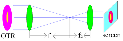
HRRL Emittance Optics Lay Out:
In this telescope system magnification will be:
So, we need to pick 2 lenses with optical length satisfy above ration. From the lower port of the 6-way cross the the floor is 94.6 cm. So, we have 90 cm place to place our camera system. So, I suggest we order camera with focal lens of 50 cm, 20, and 6, cm. These pieces can produce magnification that is small enough for experiment.
To avoid delay of experiment due to possible miscalculation, it is prudent to order 2 more lenses. One of them should be focusing and other one should be defocusing. In that case we can extend our optics as shown in following 2 figures;
Lenses for Basic Optical System Design:
| Code | Quantity | Diameter (inches) | Focal Length (cm) | Price for Each ($) | link |
| LB1723 - N-BK7 Bi-Convex Lens | 1 | 2 | 6 | 30 | [3] |
| LB1199 - N-BK7 Bi-Convex Lens | 1 | 2 | 20 | 29 | [4] |
| LB1909 - N-BK7 Bi-Convex Lens | 1 | 2 | 50 | 29 | [5] |
Sub Total Price: $88
Lenses for Extended Optical System Design (Only for Extended Part):
| Code | Quantity | Diameter (inches) | Focal Length (cm) | Price for Each ($) | link |
| LB1859 - N-BK7 Bi-Convex Lens | 1 | 2 | 100 | 29 | [6] |
| LD1613-A - N-BK7 Bi-Concave Lens | 1 | 1 | -10 | 25.90 | [7] |
Sub Total Price: $ 54.9
Optical Test
| Code | Quantity | Diameter | Focal Length (mm) | Price for Each ($) | link |
| AX76654 | 1 | 51 mm | 50 | 12.5 | [8] |
| AX76960 | 1 | 51 mm | 65 | 13.5 | [9] |
| AX27361 (6 lens) | 1 | 50 mm | +-167,+-200,+500,-333 | 11.00 | [10] |
| AX937793 | 1 | 50 mm | 100 | 4.1 | [11] |
| AX937795 | 1 | 50 mm | 200 | 3 | [12] |
Sub Total: $44.1 ($30.87, if 30% off)
Cage System ($515.7)
Cage Assembly Rod
| Code | Quantity | Length (inches) | Length (cm) | Price for Each ($) | link |
| ER2 | 4 | 2 | 5.08 | 5.9 | [13] |
| ER12 | 4 | 12 | 30.48 | 16.1 | [14] |
| ER18 | 4 | 18 | 45.72 | 25.1 | [15] |
Sub Total Price: $188.4
60 mm Cage Plates
| Code | Quantity | Price for Each ($) | link |
| LCP01 | 3 | 31.3 | [16] |
| LCP01T | 2 | 35.50 | [17] |
Sub Total Price: $164.9
LCP02 - 30 mm to 60 mm Cage Plate Adapter
| Code | Quantity | Price for Each ($) | link |
| LCP02 | 1 | 37.8 | [18] |
Sub Total Price: $37.8
LCP03 - 60 mm Blank Cage Plate
| Code | Quantity | Price for Each ($) | link |
| LCP02 | 1 | 32.6 | [19] |
Sub Total Price: $32.6
Cage Assembly Platforms
| Code | Quantity | Price for Each ($) | link |
| LCP02 | 1 | 85.10 | [20] |
Sub Total Price: $85.1
LCPA1 - 60 mm Cage Alignment Plate
| Code | Quantity | Price for Each ($) | link |
| LCP02 | 1 | 15.3 | [21] |
Sub Total Price: $15.3
Total for Cage System: $524.1
