Difference between revisions of "Emittance Test"
| Line 145: | Line 145: | ||
;Initial Accelerator Settings | ;Initial Accelerator Settings | ||
| − | E = 10 MeV | + | E = 10 MeV <math>\Rightarrow</math> Control Voltage= 4.09 V |
Pulse Width <= 50 ns | Pulse Width <= 50 ns | ||
| Line 165: | Line 165: | ||
1.) Using the quads and accelerator coils, focus the beam on the YaG crystal to as fine a spot as possible. Monitor the FC during the focusing. | 1.) Using the quads and accelerator coils, focus the beam on the YaG crystal to as fine a spot as possible. Monitor the FC during the focusing. | ||
| + | |||
| + | changed control Voltage from | ||
| + | |||
| + | Control Voltage= 4.9 V <math>\Rightarrow</math> E = 16 MeV | ||
| + | |||
| + | to | ||
| + | |||
| + | |||
| + | 4.09 V | ||
a.) Does a small beam spot size on the crystal give maximum FC signal? | a.) Does a small beam spot size on the crystal give maximum FC signal? | ||
Revision as of 18:20, 26 July 2010
Design
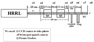
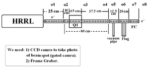
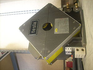
New deisign: We changed to use just one magnet.
HRRL had steer magnets on itself. We don't need external steer magnets. But Dr. Chouffani said that we might need them after quads, if the quads are not on axis. He will think about it.
File:Emittance Test Optim File.txt
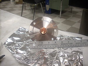
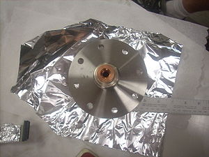
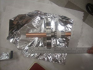
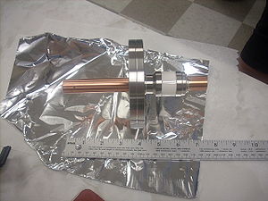
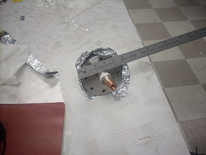
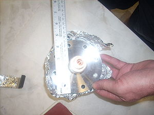
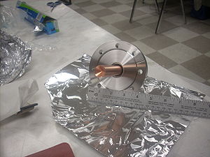
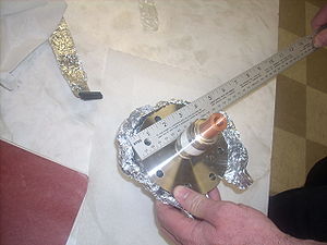
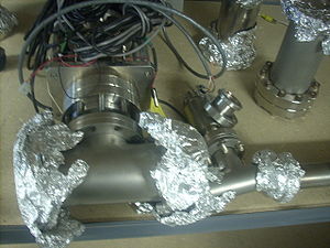
Faraday Cup
Old Beam Line
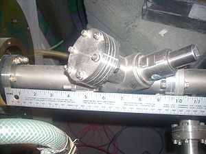
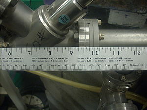
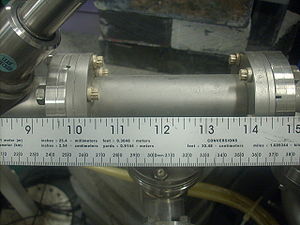
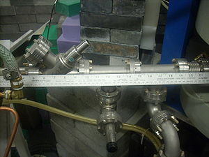
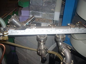
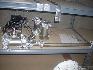
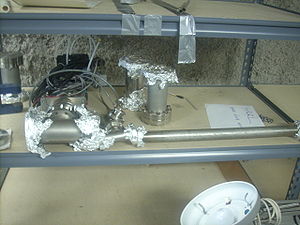
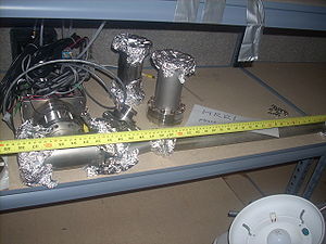
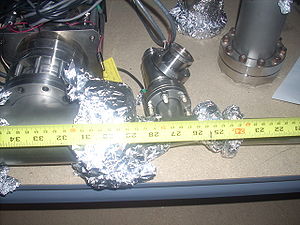
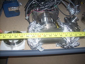
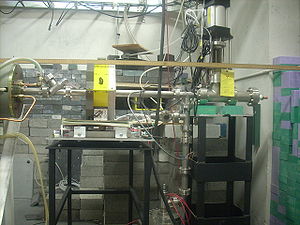
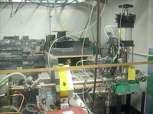
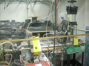
Beam Line Parts
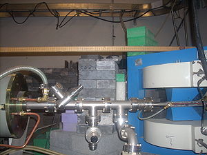
Constructed Beam Line for Emittance Test
Vacuum pressure on the beam line is less than torr (on 2010-July-7th).
Leveling Survey
Downstream of the beam up by 2.6 mm.
How to do Leveling Survey and Alignment with Theodolite on e- Beam Line
A. Leveling Beam Pipe
1. Put the theodolite as high as the center of the beam line at upstream. Turn theodolite up and down. If the up angle is equal to down angle from the center of the pipe, theodolite is exactly as high as beam pipe. If not, adjust theodolite, until up and down angles are equal.
2. Once first step finished, then rotate theodolite horizontally to down stream. Turn it up and down, if up and down angles are not equal, adjust the stand till they are equal.
B. How to Make Sure the Quad is Perpendicular to the Beam Line
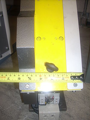
If the distances between quads and end of cavity at any given points are equal, then quad and end of cavity are parallel. Pipe is perpendicular to the end of the cavity, thus, magnet would also be perpendicular to the pipe.
I will find at lest three random points quads and three corresponding points at the end of the cavity, make sure they are equal, then I can say, magnet is perpendicular to the beam line.
I am planning to stick a metal ruler two, so two faces are parallel.
C. Centering the Quad Magnet with Theodolite
Vertical Centering
1. Finish the step 1 in A.
2. Then turn up the theodolite from the upper edge of the pipe to the magnet hole, call this angle upper angle. Do the same at lower part, call it lower angle. If the this two angles are not equal adjust the stand till they are equal.
Horizantal Centering
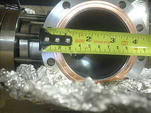
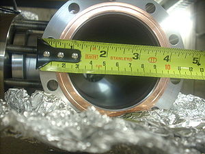
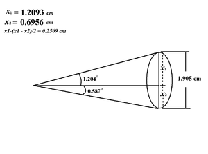
We know the diameter of the pipe . So, we can calculate from the pipe to the edge of the quad as:
We need to make sure this distance is same when measure it horizontally, so that our quad is centered on the pipe. I am going to use a ruler to ...(thinking)
July 2010 Run
- Initial Accelerator Settings
E = 10 MeV Control Voltage= 4.09 V
Pulse Width <= 50 ns
Average Beam Current = least amount needed to light up YaG crystal, start at 1 mA and Rep rate of 100 Hz.
At the same time we want to do radiation test on HRRL. This is for predicting the radiation after shifting cavity to new position. Radiation test run plan is at: [1]
7/26/10
- Alignment check
1.) Survey the Quad to be sure it is centered on the beam pipe
2.) survey the flag to determine if target is centered on the beam pipe
- Calibrate green pickup coil to FC
1.) Using the quads and accelerator coils, focus the beam on the YaG crystal to as fine a spot as possible. Monitor the FC during the focusing.
changed control Voltage from
Control Voltage= 4.9 V E = 16 MeV
to
4.09 V
a.) Does a small beam spot size on the crystal give maximum FC signal?
b.) Is there a point where the spot size changes and you can't resolve a change in the FC output?
c.) Remove the YaG target and determine if above observations are unchanged.
2.) After tuning the beam to deliver the Maximum beam current to the FC, measure the FC and green pickup coil output as a function of current by integrating the pulse with an oscilloscope.
| FC output | Green Pickup Coil output |
| (mA) | (mA) |
| 10 | |
| 20 | |
| 30 | |
| 40 | |
| 50 | |
| 60 | |
| 70 |
a.) does the FC output change with rep rate? It should not but maybe there is loss at high rates?
7/27/10
unfinished tasks from yesterday
Quad scan
First attempt to measure the spot size change as a function of Quad current
Shall we do both polarities?
| Quad Current | Beam Spot RMS (0 degrees= Left/right) | Beam Spot RMS (90 degrees= Up/Down) |
| (Amps) | (mm) | (mm) |
7/28/10
Install DAQ system to measure FC and pickup coil output with an ADC
7/29/10
repeat Quad scan
7/30/10
Open day to finish leftover tasks
Consider emittance measurements at different energies.
Go back Positrons
