Difference between revisions of "Geometry (25 MeV LINAC exit port)"
Jump to navigation
Jump to search
| Line 4: | Line 4: | ||
[[File:min_energy.png|1000px]] | [[File:min_energy.png|1000px]] | ||
| + | |||
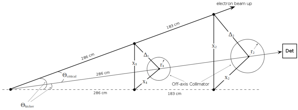
| + | critical angle:<br> | ||
| + | <math> \Theta_C = \frac{0.511\ MeV}{E\ MeV}\frac{180}{\Pi} </math> | ||
| + | |||
| + | displacements on the wall:<br> | ||
| + | <math> \Delta = 286\ \tan(\Theta_C) </math><br> | ||
| + | <math> x = \frac{\Delta}{\sqrt{2}}</math> | ||
| + | |||
| + | assume diameter of collimator is <math>\Theta/2</math> | ||
| + | <math> r = \frac{1}{2}286\ \tan{\frac{\Theta_C}{2}} <math> | ||
=25 MeV geometry= | =25 MeV geometry= | ||
Revision as of 22:47, 11 June 2010
Minimum accelerator energy to run experiment
critical angle:
displacements on the wall:
assume diameter of collimator is
kicker angle
geometry ()
collimator center position
(wall 1)
(wall 2)
collimator diameter
(wall 1)
(wall 2)
collimator critical angle
:
minimal distance from the wall ()
geometry ()
collimator center position
(wall 1)
(wall 2)
collimator diameter
(wall 1)
(wall 2)
collimator critical angle
:
minimal distance from the wall ()
Funny pictures...
how it looks 1 (, box 3"x4" and then pipe 4")
File:Vacuum pipe collimator .png
how it looks 2 (, box 3"x4" and then pipe 4")
File:Vacuum pipe collimator .png
