Difference between revisions of "Qweak GEM installation log book"
| Line 1,114: | Line 1,114: | ||
[[File:Cat6Attenuation_060-490GY.pdf]] | [[File:Cat6Attenuation_060-490GY.pdf]] | ||
| + | |||
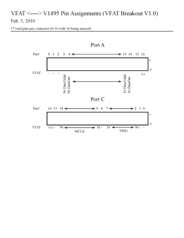
| + | =V1495 connector pin assignment= | ||
| + | |||
| + | [[File:VFAT2V1495Break1.png|600px]] | ||
Revision as of 03:44, 25 September 2010
5/12/2010
Detector installation
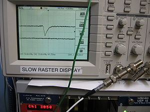
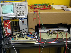
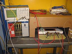
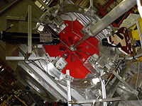
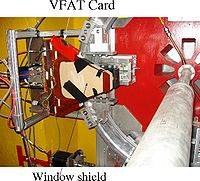
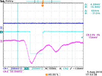
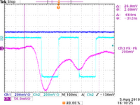
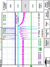
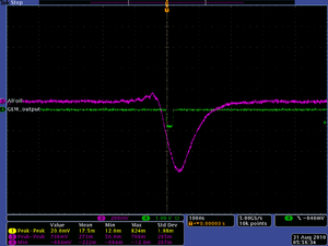
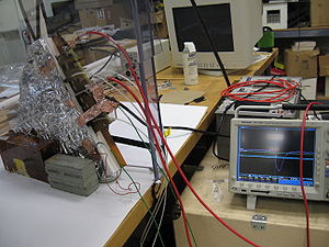
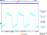
The Qweak GEM detector has been installed in the doghouce in Hall-C and the HV was turned on. On the scope picture below is shown the GEM trigger out pulse, after it has been amplified and integrated with timing filter amplifier. The high voltage supply is placed in the doghouse with the other electronics.
Electronics
We have the NIM Bin with the following modules: Leading edge discriminator, timing filter amplifier(X2), Gumstix module.
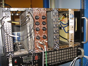
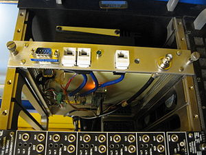
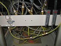
Gas
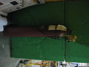
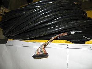
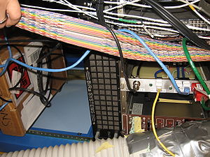
The gas bottle filled with ArCO2 is placed outside the doghouse. We have two 90 ft shielded twisted ribbon cables next to region 1 area.
cables need to be routed about colimator 2.
Bubbler
5/13/2010
Met with Kelly Tremblay to discuss survey plans. Goal is to be ready for Qweak collaborators and survey crew to align detector on June 4. The "Fork" used to connect the GEM detector to the translator will be fiducialized for the laser survey system by mounting 4 targets on the fork. The request is to have the "Y" location surveyed in to 100 microns (this is essentially ) . We desire the X-location to be surveyed within 250 microns. The Z - location beam upstream/downstream is the least critical.
DAQ computer name is : cdaql6
R1 ROC name : qwvme11 (129.57.168.81)
using the terminal server to login to the R1 ROC
- telnet hctsv11 2008
- qwvme11
- telnet hctsv11 2006
or
- telnet qwvme11
Gumstix and I2C
Brad Sawatzky: Contact for ordering gas ionfrastructure (bubbles, hose , valves,...)
5/14/2010
Gumstix sees the network now. It will be known as qwgemgumstix and have the IP address 129.57.168.91
We may also use the terminal server to login via the Gumstix's serial port but you must be logged into cdaql6 (or a computer on the same network as cdaql6)
- telnet hctsv11 2007
Runcontrol runs the cMsg server.
Gumstix contains cMsg client and subscribes to the Runcontrol cMsg server. once receiving message from ROC it then send out a message of the current thrshold value which the ROC has subscribed to . This tells the ROC to pulse again.
Carl Timmer has a sample code in C.
use Send and Get
ROC is a cMsg client as well
ROC spawns a task upon userGo and starts stepping through Discriminator setting task start a pulse and sleeps until a Mutext comes then it sends a cMsg to Gumstix
search jlab.org
nameserver 129.57.32.100
nameserver 129.57.32.101
[cdaq@cdaql6 ~]$ nslookup cdaqfs
Server:         129.57.32.100
Address:        129.57.32.100#53

Name:   cdaqfs.jlab.org
Address: 129.57.168.10

auto eth0
iface eth0 inet static
        address 129.57.168.91
        netmask 255.255.252.0
        network 129.57.168.0
broadcast 129.57.171.255
is go to the next threshold setting.
Location of Qweak coda DAQ files
Readout lists cdaq@cdaql6 ~/coda]$ ls ~/qweak/coda26/crl/
[cdaq@cdaql6 crl]$ codamaster
ROC libraries
ls ~/qweak/libraries/vme/v1495_gem/
Error message from V1495.
-> v1495ReadEvent()
0x1ad8900 (tShell): v1495ReadEvent: Error: header for word 3 from data packet != 0xE
va
qwvme11 boot parameters
The firmware is set for 32 MHz but it looks like the actual clock is 31 MHz.
boot device          : dc
unit number          : 0
processor number     : 0
host name            : cdaql6.jlab.org
file name            : /usr/local/coda/kern/5.5/vx2400_u1
inet on ethernet (e) : 129.57.168.81:fffffc00
host inet (h)        : 129.57.168.46
user (u)             : cdaq
flags (f)            : 0x20
target name (tn)     : qwvme11
startup script (s)   : /home/cdaq/qweak/coda26/boot/qwvme11.boot
5/15/10
LV1 accept to V1495 has to have a gate width at least 1 MCLK cycle less than 3 MCLK cycles.
We used cdaql6 to write several coda data files the the V1495 reading out 1 detect.
at MCLK=16MHz we created the files
v1495_28.dat.0 and v1495_29.dat.0
Run 28 was short, run 29 was very long.
I saw the following CHIP IDs in the data file but the thresholds are so high there were no hits
Card=0  ChipID=0xa6c
i = 14
Card=1  ChipID=0x8ec
i = 28
Card=2  ChipID=0x8ec
i = 42
Card=3  ChipID=0x6ec
i = 56
Card=4  ChipID=0x0
i = 70
Card=5  ChipID=0x66c
Its seems Card 4 is not getting its ID recorded but its I2C is responding. Perhaps a failed card? We loer MCLK to 8 MHz no change.
Summary
Successes:
Two R1 detectors reside outside the Hall C doghouse. One detector was running in the doghouse and cosmic signals were observed which went away when turning the drift voltage down to equal the GEM preamplifier voltage (this is how we convince ourself that the signal is real without turning the detector completely off).
A data file was written using CODA v 2.6 installed on cdaql6 and the GW ROC. The MCLK signal however needed to be set to 16 MHz instead of 32 MHz. The V1495 was unable to "lock on " to the 32 MHz signal from the G0 clock. It is not understood why at this time. While sampling the data at 16 MHz is not a show stopper we will try to find a way to operate at 32 MHz. The same V1495 was able to lock onto our 32 MHz pulser at ISU without a problem.
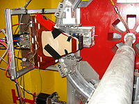
A GEM detector was mounted on the rotator and was able to rotate 360 degrees freely. There was some concern that the Breakout board would hit a bolt coming up from the floor which secures the first collimator. There is at least a 3 inch gap between this bolt and the breakout board at the point of closest approach. A substantial amount of the bolt thread extends well beyond the nut. A request will be made to cut off the excess bolt that extends beyond the nut.
Failures:
We are unable to record the VFAT output in the V1495 using the ribbon cables provided by JLab. The V1495 was no longer able to recorded the output of 3 VFAT cards when we switched from our 4 foot long, shielded, flat ribbon cables to JLab's 100 ft long rounded ribbon cables. We have seen this before. We had similar problems at ISU and found that they went away when a twisted pair FLAT ribbon cable was used. Signal integrity becomes important at the 40 MHz frequencies.
Path forward:
We will try to debug breakout board with VFAT electronics, the V1495, and two JLab shielded ribbon cables at ISU to determine if JLab's cables are not usable. We did successfully test the readout using 100 ft FLAT twisted pair cables during ISU beam tests. If the FLAT cables must be used then we will need to coordinate with Klaus on the cable holder to determine if the holder can accommodate flat cables or if we can use the rounded cables for the last meters of slack used by the cable holder.
6/13/10
7/29/10
8/4/10
PRETRGe&EN1 scaler in Hall C counting house pannel port 6.
The Trig out of GEM A and B went into chanels 4 & 5 of the same scaler used for Alena's scintillator which records it values in the ROC file bank ID0x0403
Power strip control to reboot Hall C equipment can be accessed from the counting room computer
https://hallcweb.jlab.org/wiki/index.php/Hall_C_Network
Check V1495
To check if the V1495 is installed I logged into the ROC from cdaql1
[cdaq@cdaql1 ~]$ telnet qwvme11
->v1495Init(0x09330000)
The V1495 address was set to 0811 so I changed it to 0933
Now I see that it is initializing
-> v1495Init(0x09330000)
0x1b09070 (tShell): v1495Init: v1495 Module has been successfully initialized.

0x1b09070 (tShell): v1495 module has been reset:

value = 0 = 0x0
It seems I have the old I2C gumstix to Breakboard card and not the right RJ45 connector to allow me to talk I2C to the VFAT card (unless the VFAT card has gone bad). Effort to make my own cable according to Tamuna's pinout chart failed.
7/5/10
DAQ
Paul and I were able to get CODA 2.6.1 to initialize the V1495 upon PRESTART. Apparently there is a problem running more than 1 DAQ at a time on different computers (perhaps they are trying to use the same rcServer?).
Detector
A GEM trigout signal is going upstairs to the scope. The timing amplifier downstairs is set to integrate the pulse over 100 ns. Is this why I see 600 ns Comsic pulses? I will check this with beam tomorrow morning.
I will use the discriminated output of HALO3 to determine if there is beam coming down the beamline and LUMI3 to determine if a target is in.
The HV for the above monitors may be observed through EPIC on cdaql6 with the following commands
- login to cdaql6
- ssh cvswrks@cdaql6
- /net/cdaqfs/home/EPICS/dvlepics/llapp/CaenHV/1-0/QWEAK/tk/hv.tcl
First Beam
I saw signals associated with an electron beam into Hall C for the first time today. The beam was being tuned and the detector was out of position so any signals were mostly background. The HV was -3600 Volts on the drift and -3300 Volts on the GEM preamplifier. The Trigout pulse was amplified in the doghouse by an Ortec timing amplifier set to integrate the signals over a 100 ns period.
7/6/10
GEM Timing Amp
The Ortec timing amplifier used to send the GEM output upstairs has an integrate time of 100 ns. The Phillips discriminator has a maximum output width of about 100 ns and we do see double pulsing sometimes so be careful. The max rate for a 50 ns GEM pulse is 20 MHz but the preamp width of 600 ns keeps us below 1 MHz, and the discriminator width of 100 ns keeps us below 10 MHz.
With a 1 mil Aluminum target, the 10 MHz max rate may be at a beam current of 50 nA.
Add GEM scaler to MAP
login to cdaql4
cd $QWANALYSIS/Tracking/prminput/
The file
detectors.map
describes all the detectors used below are two relevant examples
[QwGasElectronMultiplier]
 name = R1
 map = qweak_R1.map
 geom = qweak_new.geo
[QwTriggerScintillator]
 name = TS
 map = qweak_trigscint_channel.map
 geom = qweak_new.geo
 mask = 0xffff
The scalers used for the GEM trigout pulse are plugged into the trigger scintillator scalers so I edited the file to look like this
sca_bank=0x0403
! module.type  module.num  chan.num, det.type, det.name
  SIS3801, 0,  0, trigscint, ts2m_sca
  SIS3801, 0,  1, trigscint, ts2p_sca
  SIS3801, 0,  2, trigscint, ts1m_sca
  SIS3801, 0,  3, trigscint, ts1p_sca
  SIS3801, 0,  4, trigscint, GEMTrigOut_Naovoo_sca
  SIS3801, 0,  5, trigscint, GEMTrigOut_Urim_sca
  SIS3801, 0,  6, trigscint, ts2mt_sca
  SIS3801, 0,  7, trigscint, ts1mt_sca
The ROOT files are stored in
cd $QW_ROOTFILES
and named as QWEAK_runNumber.000.root
To reanalyze the tracking data without doing tracking go to the data directory
cd $QW_DATA/
 qwtracking -r 724 --QwTracking.disable-tracking
The Scaler is read out at fixed time intervals but those intervals can change depending on helicity flip rate and if a "fake" helicity flip rate is being used.
R1 Timing
R1 rate -vs- beam current
| Run # | Scint | Naovoo |
19-08-2010
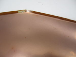
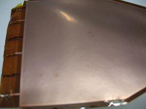
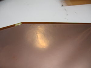
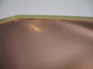
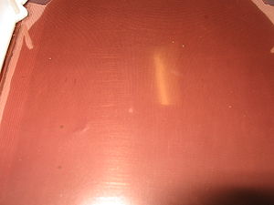
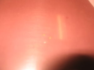
Took detector apart. GEM foils(all of them) are bunt. Some of the strips have discoloration, they have burnt spots.
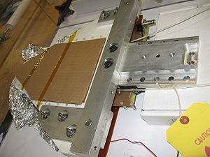
The images below show all the GEM foils and PC board.
During the beam tuning at JLab, when all tracking chambers were in place, I saw the following on trigout with the detector off.
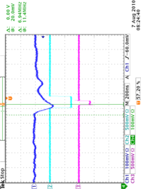
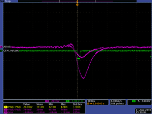
Channel 3 (purple) is the trigout signal from the GEM detector. I believe Channel 2 was the Qweak scintillator and Channel 1 was a Halo monitor. I have never seen such an output from the GEM detector when exposed to beam. It seems we are unable to have the GEM detector in place when the pulsed 10 mA beam is tuning. I suspect this killed the detector on Aug 6.
20-08-2010
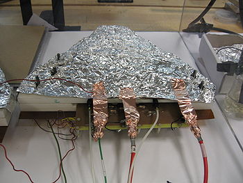
Gas was flowing through both detectors today. In order to reduced the pick up noise, It was suggested to wrap detectors into the aluminum foil.
Tomorrow is a power shutdown in EEL, CEBAF and some other building. I will be unable to work there. I will get the scaler from counting room.
Urim
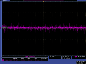
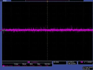
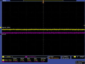
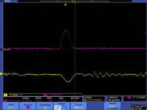
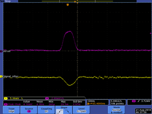
Below are the scope images of the noise before and after aluminum foil:
Signals from the detector are following:
Nauvoo
Turned Nauvoo on today. Foils were changed yesterday. When looking at TrigOut instead of seeing the positive pulse i am getting negative pulse, and no signal on strips. The last GEM foil acts like an anode(it collects the charge). I forgot to take the scope picture, but thats what i observed.
22-08-2010
Changed the shorted GEM foil on Nauvoo, but still no positive signal on TrigOut. I saw negative signal.
23-08-2010
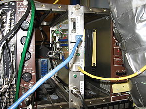
Today worked on I2C. Gumstix, I2C board and power supply were installed in the NIM module. NIM module is in the NIM bin. The breakout box and two VFATs(64 and 112) are in the box under the NIM bin.
Got Timing Filter Amplifier, couldnt find scaler. There was no use for integrator on Timing Filter Amplifier.
Nauvoo detector is open right now. I will apply voltage on GEM tomorrow and check the voltages again across the GEM foils.
24-08-2010
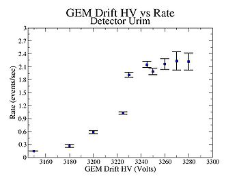
Urim measurements
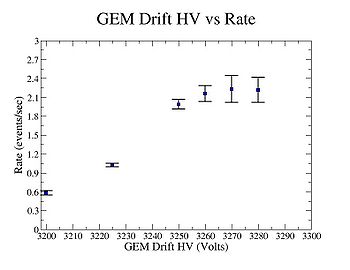
Got scaler and discriminator. Made measurements of GEM drift voltage vs rate. Used only cosmic rays.
The result is shown below:
The rate only doubled Dr. Forest. I did it for 3270 Volts.
Urim should be ready to install in Hall C after you try a source and wrap it in tin foil. Cut an opening in the tin foil for a window.
Fe-55 Source use
Activity of Gamma, x-ray source. as of 6/24/04.
Half life = 2.73 years
keV
TORI Data (1999) Gammas from 55Fe (2.73 y 3)
Eg (keV) Ig (%) Decay mode 125.95 1 1.28E-7 2 e
X-rays from 55Fe (2.73 y 3)
E (keV) I (%) Assignment
0.556 0.037 10 Mn Ll
0.568 0.025 6 Mn Lh
0.637 0.028 7 Mn La2
0.637 0.25 6 Mn La1
0.640 0.0022 6 Mn Lb6
0.648 0.19 5 Mn Lb1
0.720 0.011 3 Mn Lb4
0.720 0.017 5 Mn Lb3
5.770 6.9E-06 4 Mn Ka3
5.888 8.5 4 Mn Ka2
5.899 16.9 8 Mn Ka1
6.490 1.01 5 Mn Kb3
6.490 1.98 10 Mn Kb1
6.536 0.00089 5 Mn Kb5
6.539 8.5E-08 5 Mn Kb4
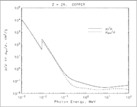
NIST data tables says:
A .125 MeV photon has a Range in copper of =
Density Copper =
Range = mils
How thick is the GEM copper cathode?
Definition of Range:
- Def of Range (R)
- The distance traveled before all the particles energy is lost.
- = theoretical calculation of the path length traveled by a particle of incident energy
- Note units:
At 0.126 MeV
If the copper is 5 microns thick then
photon energy would be about 20 keV when it sees drift region
What is Cathode thickness?
Is the Fe-55 source sealed or open. Sealed source would attenuate photons more.
The fraction of photons surviving a distance x is given by
where
= total absorption coefficient = 1/(mean free path) =
N = Avagadros number = density of copper A = molar weight = cross-section per atom
A 6 keV photon has = 1027.6 /cm
A 126 keV photon has ~ 3 /cm
If the copper cathode is 5 microns and not 50
the link below takes you to the mass attenuation coefficients for copper
http://physics.nist.gov/PhysRefData/XrayMassCoef/ElemTab/z29.html
The 2nd column is the mass attenuation coefficient and the third column is the energy absorption coefficient
Copper Z = 29
____________________________________

     Energy
      (MeV)      (cm2/g)     (cm2/g)
____________________________________

   1.00000E-03  1.057E+04  1.049E+04
   1.04695E-03  9.307E+03  9.241E+03
   1.09610E-03  8.242E+03  8.186E+03
L1 1.09610E-03  9.347E+03  9.282E+03
   1.50000E-03  4.418E+03  4.393E+03
   2.00000E-03  2.154E+03  2.142E+03
   3.00000E-03  7.488E+02  7.430E+02
   4.00000E-03  3.473E+02  3.432E+02
   5.00000E-03  1.899E+02  1.866E+02
   6.00000E-03  1.156E+02  1.128E+02
   8.00000E-03  5.255E+01  5.054E+01
   8.97890E-03  3.829E+01  3.652E+01
K  8.97890E-03  2.784E+02  1.824E+02
   1.00000E-02  2.159E+02  1.484E+02
   1.50000E-02  7.405E+01  5.788E+01
   2.00000E-02  3.379E+01  2.788E+01
   3.00000E-02  1.092E+01  9.349E+00
   4.00000E-02  4.862E+00  4.163E+00
   5.00000E-02  2.613E+00  2.192E+00
   6.00000E-02  1.593E+00  1.290E+00
   8.00000E-02  7.630E-01  5.581E-01
   1.00000E-01  4.584E-01  2.949E-01
   1.50000E-01  2.217E-01  1.027E-01
   2.00000E-01  1.559E-01  5.781E-02
   3.00000E-01  1.119E-01  3.617E-02
   4.00000E-01  9.413E-02  3.121E-02
   5.00000E-01  8.362E-02  2.933E-02
   6.00000E-01  7.625E-02  2.826E-02
   8.00000E-01  6.605E-02  2.681E-02
   1.00000E+00  5.901E-02  2.562E-02
   1.25000E+00  5.261E-02  2.428E-02
   1.50000E+00  4.803E-02  2.316E-02
   2.00000E+00  4.205E-02  2.160E-02
   3.00000E+00  3.599E-02  2.023E-02
   4.00000E+00  3.318E-02  1.989E-02
   5.00000E+00  3.177E-02  1.998E-02
   6.00000E+00  3.108E-02  2.027E-02
   8.00000E+00  3.074E-02  2.100E-02
   1.00000E+01  3.103E-02  2.174E-02
   1.50000E+01  3.247E-02  2.309E-02
   2.00000E+01  3.408E-02  2.387E-02
Setting on Amplifier and discriminator:
Amplification is X20 and 10 on a nub. Integration=20ns and diff=out. Pulse divided, one and goes to discriminator and the other one into the scope. The discriminator threshold is set to 45 mV.
Nauvo
High Voltage distribution for GEM.
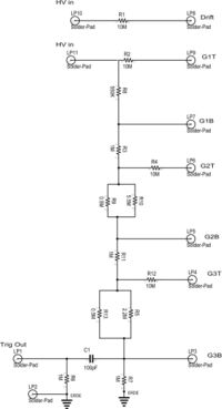
Applied 500 Volts on GEM.
The measured voltage on each side of the each GEM foil is presented in a table.
| GEM Foil | Measured Voltage(Volts) Nauvoo | Measured 10 x 10 cm Board Voltage |
|---|---|---|
| VGem in | 500 | 500 |
| G1T | 256 | 248 |
| G1B | 422 | 473 |
| G2T | 148 | 232 |
| G2B | 237 | 415 |
| G3T | 78 | 217 |
| G3B | 104 | 371 |
I was expecting the voltage to decrease with respect to ground as you go down the voltage divider.
It is decreasing. By G3 i mean the last GEM foil.
27-08-2010
Got CAT5 cable for I2C. Need connectors.
Changed resistors on HV board of Nauvoo, still no luck. Had to take open Urim, to check the voltage distribution, it is the same as on Nauvoo.
Dont know what is the reason, the foils are new.
Instead of positive pulse getting negative pulse on trigout again.
30-08-2010
Nauvoo
Works since yesterday. Changed foils.
Voltage = 3475/3200 Volts
Amplification= X20, 12.5 on a nub.
Integration=20ns
Diff=out
Discriminator threshold = 80 mV
| Time (mints) | # Counts | Rate (Number of Events/sec) |
| 13 | 1002 | 1.28 |
| 16 | 1233 | 1.28 |
| 14 | 914 | 1.1 |
(Numberof#/sec)
Urim
Voltage setting on Urim = 3245/2945 Volts
| Time (mints) | # Counts | Rate (Number of Events/sec) |
| 11 | 1357 | 2.056 |
| 7 | 859 | 2.045 |
| 7 | 862 | 2.052 |
Vertical vs Horizontal
| Position | Rate (Number of Counts/sec) |
| Vertical | |
| Horizontal |
The bracket is attached to Urim.
Remaining tasks
bubbler holder , need 2 more shielded ribbon cable, new aluminum foil for detector in order to shield it.
High Voltage Supply: The channel number 2 on hv supply doesnt go above 3000Volts. Suggest, to use 0 and 1 channels for Nauvoo and 3&&2 for Urim.
There is only one new breakout box in Hall, need to bring second one.
1.)check cosmic rate on both detectors and measure noise ( max 10 mV peak to peak)
| Detector | Drift HV | GEM HV |
| Urim | -3245 | -2945 |
| Nauvoo | -3450 | -3150 |
2.) Attach adapter boards
3.)I2C checkout
4.) Look into Al shielding
5.) install shielded ribbon cables, work on readout
6.) install bubbler if still not done.
Co-60 source
A Co-60 source was placed on top of the GEM detector kapton foil window. The button source activity was 0.6 microCurie in 2004. The source generated a rate of 70 Hz.
Activity of Gamma source. as of 6/24/04.
Half life = 5 years
According to http://ie.lbl.gov/toi/nuclide.asp?iZA=270060
Co-60 activity is from mainly 2 photons 1173.237 keV and 1332.501 keV.
A 1.2 MeV photon has0.465 /cm
If the above is correct , the Co-60 source is emitting 1.2 MeV photons at a rate of 6.5 kHz.
9-18-10
Use cdaq@cdaql6 to readout V1495.
terminal server port
To get to qwvme11
telnet hctsv7 2006
To go to Gumstix
telnet hctsv11 2005
Checking I2C controls
ssh root@qwgemgumstix
cd bin
ports 112 and 64 have VFAT cards on them
flipping sleep block for VFAT at I2C address 64
echo "p 64 0 0 flip" | ./flipbit.arm
echo "p 112 0 0 flip" | ./flipbit.arm
The 2 VFAT cards are responding.
My SCSI doesn't seem to work anymore with my powerbook. Try to debug tonight.
I got the DAQ running on cdaql6.
I am sending a trigger down to the V1495 which triggers the VFAT cards.
I got the error message on the ROC
interrupt: v1495ReadEvent: Error: header for word 3 from data packet != 0xE
EB1 crashed. I am triggering at about 200 Hz.
Wrote data file
Paul King paid me a visit and corrected my CODA choices so I could write a file. Apparently I had chosen Session and Run configuration wrong
Proper CODA settings for standalone V1495 runnging
Session = cdaq
COOL configureation = V1495_l6
To start DAQ
1.) run codamaster
2.)choose v1495_l6 from the EXPID menu presented by coda master
3.) launch all the components
4.) choose "V1495_l6" from the session menu in runcontorl
5.) select the "cool" menu from the "Configuration" menu.
then select "V1495_l6" from the popup menu
6.) follow the usual download, prestart , and run
wrote the data file
[cdaq@cdaql6 ~]$ ls -lh /local/data1/v1495_l6_5424.dat.0
-rw-r--r-- 1 cdaq c-cdaq 64K Sep 18 19:50 /local/data1/v1495_l6_5424.dat.0
All is not perfect. I get the error message
interrupt: v1495ReadEvent: dataFIFO is empty
It looks like the VFAT is missing some of the triggers I send it when I look on the scope.
Try to debug tomorrow by doing single triggers and use the functions
v1495DataReady(0
the above function should return the number of events waiting to be read out. So hit the trigger button and make sure the above function returns the value of "1"
Then use the command
-> v1495StatusPrint
0x1b090b0 (tShell): V1495[0]: #B[24] #F[1/131] B/s[24] F/s[1]
0x1b090b0 (tShell):   LastCap[12]: 0x1b090b0 (tShell): A2AC 0x1b090b0 (tShell): C720 0x1b090b0 (tShell): 0A71 0x1b090b0 (tShell): 0000 0x1b090b0 (tShell): 0000 0x1b090b0 (tShell): 0000 0x1b090b0 (tShell): 0000 0x1b090b0 (tShell): 0000 0x1b090b0 (tShell): 0000 0x1b090b0 (tShell): 0000 0x1b090b0 (tShell): 0000 0x1b090b0 (tShell): 907D 0x1b090b0 (tShell):
0x1b090b0 (tShell): Event Count: 114 ; Chip ID : 0xA71
0x1b090b0 (tShell): value = 32 = 0x20 = ' '
-> V1495[1]: #B[0] #F[0/0] B/s[0] F/s[0]
0x1b090b0 (tShell):   LastCap[0]: 0x1b090b0 (tShell):
0x1b090b0 (tShell): V1495[2]: #B[0] #F[0/0] B/s[0] F/s[0]
0x1b090b0 (tShell):   LastCap[0]: 0x1b090b0 (tShell):
0x1b090b0 (tShell): V1495[3]: #B[0] #F[0/0] B/s[0] F/s[0]
0x1b090b0 (tShell):   LastCap[0]: 0x1b090b0 (tShell):
0x1b090b0 (tShell): V1495[4]: #B[0] #F[0/0] B/s[0] F/s[0]
0x1b090b0 (tShell):   LastCap[0]: 0x1b090b0 (tShell):
0x1b090b0 (tShell): V1495[5]: #B[24] #F[1/131] B/s[24] F/s[1]
0x1b090b0 (tShell):   LastCap[12]: 0x1b090b0 (tShell): A2AC 0x1b090b0 (tShell): C720 0x1b090b0 (tShell): 5CEA 0x1b090b0 (tShell): 0000 0x1b090b0 (tShell): 0000 0x1b090b0 (tShell): 0000 0x1b090b0 (tShell): 0000 0x1b090b0 (tShell): 0000 0x1b090b0 (tShell): 0000 0x1b090b0 (tShell): 0000 0x1b090b0 (tShell): 0000 0x1b090b0 (tShell): 74A8 0x1b090b0 (tShell):
0x1b090b0 (tShell): Event Count: 114 ; Chip ID : 0xCEA
You should see chip IDs like above.
9/19/10
Missing triggers
I noticed yesterday that some triggers did not return data packets. Let's try to debug this.
I have 2 VFAT cards in port 64 and 112. As seen from yesterday using the v1495 library function v1495StatusPrint() on the ROC The CHIP ID's are 0xCEA and 0xA71. This agrees with what I2C is telling me.
I will now give the Readout one trigger at a time and check if the V1495 has any data on it using the
v1495DataReady()
function.
First run the script VFAT.setup from the qwgemgumstix. The script is in the subdirectory /home/root/bin
/home/root/bin/VFAT.setup
Now I will work from the ROC.
First Initialize the V1495
 -> v1495Init(0x09330000)
0x1b08930 (tShell): v1495Init: v1495 Module has been successfully initialized.

0x1b08930 (tShell): v1495 module has been reset:

value = 0 = 0x0
Now I reset the v1495 module to clear all its buffers
-> v1495Reset()
0x1b08930 (tShell): v1495 module has been reset:

value = 0 = 0x0
Now Check to see if there is any data before I push the single trigger button on the gate generator.
-> v1495DataReady()
value = 0 = 0x0
Now push the trigger button once
-> v1495DataReady() value = 1 = 0x1
Now I check what is in the buffer using
-> v1495StatusPrint()
0x1b08930 (tShell): V1495[0]: #B[24] #F[1/2] B/s[24] F/s[1]
0x1b08930 (tShell):   LastCap[12]: 0x1b08930 (tShell): AE46 0x1b08930 (tShell): C010 0x1b08930 (tShell): 0A71 0x1b08930 (tShell): 0000 0x1b08930 (tShell): 0000 0x1b08930 (tShell): 0000 0x1b08930 (tShell): 0000 0x1b08930 (tShell): 0000 0x1b08930 (tShell): 0000 0x1b08930 (tShell): 0000 0x1b08930 (tShell): 0000 0x1b08930 (tShell): 1C38 0x1b08930 (tShell):
0x1b08930 (tShell): Event Count: 1 ; Chip ID : 0xA71
0x1b08930 (tShell): V1495[1]: #B[0] #F[0/0] B/s[value = 0] F/s[032]
0x1b08930 (tShell = 0x):   LastCap[020]: 0x1b08930 (tShell = '):
0x1b08930 ( tShell): V1495[2]: #B['0] #F[0/0] B/s[
0] F/s[0]
0x1b08930->  (tShell):   LastCap[0]: 0x1b08930 (tShell):
0x1b08930 (tShell): V1495[3]: #B[0] #F[0/0] B/s[0] F/s[0]
0x1b08930 (tShell):   LastCap[0]: 0x1b08930 (tShell):
0x1b08930 (tShell): V1495[4]: #B[0] #F[0/0] B/s[0] F/s[0]
0x1b08930 (tShell):   LastCap[0]: 0x1b08930 (tShell):
0x1b08930 (tShell): V1495[5]: #B[24] #F[1/2] B/s[24] F/s[1]
0x1b08930 (tShell):   LastCap[12]: 0x1b08930 (tShell): AE46 0x1b08930 (tShell): C010 0x1b08930 (tShell): 5CEA 0x1b08930 (tShell): 0000 0x1b08930 (tShell): 0000 0x1b08930 (tShell): 0000 0x1b08930 (tShell): 0000 0x1b08930 (tShell): 0000 0x1b08930 (tShell): 0000 0x1b08930 (tShell): 0000 0x1b08930 (tShell): 0000 0x1b08930 (tShell): F8ED 0x1b08930 (tShell):
0x1b08930 (tShell): Event Count: 1 ; Chip ID : 0xCEA
I see the CHIP ID's which I saw when using the I2C interface.
- Note
- Data is still wiating to be readout, doing the above function did not alter the V1495 buffers
-> v1495DataReady() value = 1 = 0x1
To move the data out of the v1495 buffers you can do a ReadEvent
-> v1495DataReady()
value = 1 = 0x1
-> v1495ReadEvent()
value = 84 = 0x54 = 'T'
-> v1495DataReady()
value = 0 = 0x0
-> v1495ReadEvent()
0x1b08930 (tShell): v1495ReadEvent: dataFIFO is empty
value = 0 = 0x0
I sent trigger to the v1495 and monitored the scope output.
Whe I started I observed that about 30% of the triggers were missed as seen on the scope.
Changing the shielded cable to an unshielded seemed to drop that to 10%. Perhaps the missed triggers are cable related.
I think I will put connectors onto the new shielded ribbon cable and see if things improve.
Rad damage to VFAT chip?
I took out the two working VFATs and inserted a VFAT card which was in the R1 hut during the summer commissioning run.
- Observation
- I2C was still working, I could set registers, but I did not observe any LVDS output (I believe it was not working before though).
Test 2nd breakout box
- NEED TO BRING MORE JUMPERS
- Tamuna's NIM Module only has 1 power output. Should we tee it off to supply 2 breakout boxes, I am not sure if it can supply the current. May need to test
I think you cant tee it.
It depends on how much current the power supply is rated for. I think we need at least 1.2 mA per breakout board. So if the power supply delivers 3 mA and maintains 2.5 volts we would be able to tee it.
I wonder if Warren put in the voltage protection diodes in the latest version of the breakout board?
I think I also need to work on the I2C control of 2 boards with one gumstix or I could ask Tamuna to build another NIM module.
Test 2nd breakout box in R1 Hut
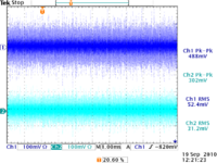
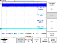
It seems there is a lot of pickup on the flat ribbon cable (peak-peak noise of about 400 mv with and RMS of 40 mv).
Now hook a ground wire between the scope and a Ground pole in Hall C.
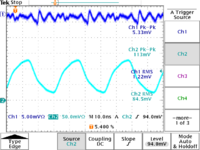
BNC trig out cable is on Channel 1, not hooked to anything. Grounding the scope reuces the noise to 60 mV peak-peak.
The unshielded ribbon cable is hooked to Channel 2
BNC trig out cable is on Channel 1, not hooked to anything
The unshielded ribbon cable is hooked to Channel 2
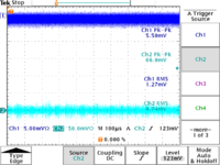
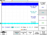
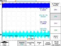
The shield from a shielded ribbon cable is attached to Scope.
Shielded cable ungrounded
Shielded cable grounded
16 MHz LVDS clock on either shielded flat fibbon cable or unshielded with shielded ribbon cable grounded to scope
16 MHz LVDS clock straight out of V1495
- Conclusion
- The clock pulse is being attenuated by a factor of 3. You need 200 mV differentials to drive LVDS and both cables attenuate the pulse to below 130 mV.
- The grounding the ribbon cable shield to the scope drops the noise from 400 to at least 30 mV. Similar noise reduction was observed if you only use shielded cable in the R1 hut area.
9/20/10
Made new shieled ribbon cables to take signals from breakout board to VFAT cards
started taking a run with VTAS plugged into 16 and 112
/local/data1/v1495_l6_5429.dat.0
I think the FIFO empty messages started killed the DAQ after about 200 events.
maybe its because the trigger pulse was not 1.4 clock pulses wide.
Make HClog entry for Paul King
9/24/10
Cat 6 -vs- ribbon cable attenuation
The 28 guage ribbon cable wire attenuates a 20 MHz signal 4.8 dB/100 ft.
File:BELDEN WIRE AND CABLE 214-3078.PDF
The scope observations from 9/19/10 suggest that
dB = 20 log(400 mV/120 mV) = 10.45 dB/100 ft > 4.8 dB/100 ft?
Cat 6 attenuates 20 MHz signal 2.2 dB/100 ft (careful units are in meters in document below)
File:Cat6Attenuation 060-490GY.pdf
