Difference between revisions of "Qweak GEM installation log book"
(→7/5/10) |
(→7/6/10) |
||
| Line 273: | Line 273: | ||
=7/6/10= | =7/6/10= | ||
| + | |||
| + | ==GEM Timing Amp== | ||
| + | |||
| + | The Ortec timing amplifier used to send the GEM output upstairs has an integrate time of 100 ns. The Phillips discriminator has a maximum output width of XXXX ns and we do see double pulsing sometimes so be careful. The max rate for the GEM is likely 10 MHz. | ||
Revision as of 12:29, 6 August 2010
5/12/2010
Detector installation
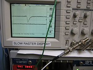
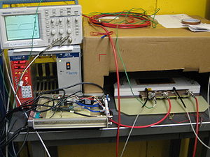
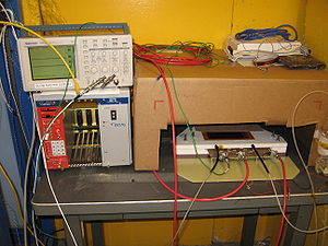
The Qweak GEM detector has been installed in the doghouce in Hall-C and the HV was turned on. On the scope picture below is shown the GEM trigger out pulse, after it has been amplified and integrated with timing filter amplifier. The high voltage supply is placed in the doghouse with the other electronics.
Electronics
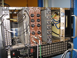
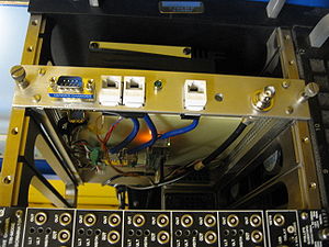
We have the NIM Bin with the following modules: Leading edge discriminator, timing filter amplifier(X2), Gumstix module.
Gas
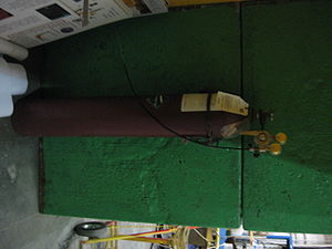
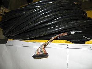
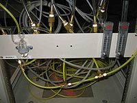
The gas bottle filled with ArCO2 is placed outside the doghouse. We have two 90 ft shielded twisted ribbon cables next to region 1 area.
cables need to be routed about colimator 2.
Bubbler
5/13/2010
Met with Kelly Tremblay to discuss survey plans. Goal is to be ready for Qweak collaborators and survey crew to align detector on June 4. The "Fork" used to connect the GEM detector to the translator will be fiducialized for the laser survey system by mounting 4 targets on the fork. The request is to have the "Y" location surveyed in to 100 microns (this is essentially ) . We desire the X-location to be surveyed within 250 microns. The Z - location beam upstream/downstream is the least critical.
DAQ computer name is : cdaql6
R1 ROC name : qwvme11 (129.57.168.81)
using the terminal server to login to the R1 ROC
- telnet hctsv11 2008
- qwvme11
- telnet hctsv11 2006
or
- telnet qwvme11
Gumstix and I2C
Brad Sawatzky: Contact for ordering gas ionfrastructure (bubbles, hose , valves,...)
5/14/2010
Gumstix sees the network now. It will be known as qwgemgumstix and have the IP address 129.57.168.91
We may also use the terminal server to login via the Gumstix's serial port but you must be logged into cdaql6 (or a computer on the same network as cdaql6)
- telnet hctsv11 2007
Runcontrol runs the cMsg server.
Gumstix contains cMsg client and subscribes to the Runcontrol cMsg server. once receiving message from ROC it then send out a message of the current thrshold value which the ROC has subscribed to . This tells the ROC to pulse again.
Carl Timmer has a sample code in C.
use Send and Get
ROC is a cMsg client as well
ROC spawns a task upon userGo and starts stepping through Discriminator setting task start a pulse and sleeps until a Mutext comes then it sends a cMsg to Gumstix
search jlab.org
nameserver 129.57.32.100
nameserver 129.57.32.101
[cdaq@cdaql6 ~]$ nslookup cdaqfs
Server:         129.57.32.100
Address:        129.57.32.100#53

Name:   cdaqfs.jlab.org
Address: 129.57.168.10

auto eth0
iface eth0 inet static
        address 129.57.168.91
        netmask 255.255.252.0
        network 129.57.168.0
broadcast 129.57.171.255
is go to the next threshold setting.
Location of Qweak coda DAQ files
Readout lists cdaq@cdaql6 ~/coda]$ ls ~/qweak/coda26/crl/
[cdaq@cdaql6 crl]$ codamaster
ROC libraries
ls ~/qweak/libraries/vme/v1495_gem/
Error message from V1495.
-> v1495ReadEvent()
0x1ad8900 (tShell): v1495ReadEvent: Error: header for word 3 from data packet != 0xE
va

== qwvme11 boot parameters==
The firmware is set for 32 MHz but it looks like the actual clock is 31 MHz.
boot device          : dc
unit number          : 0
processor number     : 0
host name            : cdaql6.jlab.org
file name            : /usr/local/coda/kern/5.5/vx2400_u1
inet on ethernet (e) : 129.57.168.81:fffffc00
host inet (h)        : 129.57.168.46
user (u)             : cdaq
flags (f)            : 0x20
target name (tn)     : qwvme11
startup script (s)   : /home/cdaq/qweak/coda26/boot/qwvme11.boot
5/15/10
LV1 accept to V1495 has to have a gate width at least 1 MCLK cycle less than 3 MCLK cycles.
We used cdaql6 to write several coda data files the the V1495 reading out 1 detect.
at MCLK=16MHz we created the files
v1495_28.dat.0 and v1495_29.dat.0
Run 28 was short, run 29 was very long.
I saw the following CHIP IDs in the data file but the thresholds are so high there were no hits
Card=0  ChipID=0xa6c
i = 14
Card=1  ChipID=0x8ec
i = 28
Card=2  ChipID=0x8ec
i = 42
Card=3  ChipID=0x6ec
i = 56
Card=4  ChipID=0x0
i = 70
Card=5  ChipID=0x66c
Its seems Card 4 is not getting its ID recorded but its I2C is responding. Perhaps a failed card? We loer MCLK to 8 MHz no change.
Summary
Successes:
Two R1 detectors reside outside the Hall C doghouse. One detector was running in the doghouse and cosmic signals were observed which went away when turning the drift voltage down to equal the GEM preamplifier voltage (this is how we convince ourself that the signal is real without turning the detector completely off).
A data file was written using CODA v 2.6 installed on cdaql6 and the GW ROC. The MCLK signal however needed to be set to 16 MHz instead of 32 MHz. The V1495 was unable to "lock on " to the 32 MHz signal from the G0 clock. It is not understood why at this time. While sampling the data at 16 MHz is not a show stopper we will try to find a way to operate at 32 MHz. The same V1495 was able to lock onto our 32 MHz pulser at ISU without a problem.
A GEM detector was mounted on the rotator and was able to rotate 360 degrees freely. There was some concern that the Breakout board would hit a bolt coming up from the floor which secures the first collimator. There is at least a 3 inch gap between this bolt and the breakout board at the point of closest approach. A substantial amount of the bolt thread extends well beyond the nut. A request will be made to cut off the excess bolt that extends beyond the nut.
Failures:
We are unable to record the VFAT output in the V1495 using the ribbon cables provided by JLab. The V1495 was no longer able to recorded the output of 3 VFAT cards when we switched from our 4 foot long, shielded, flat ribbon cables to JLab's 100 ft long rounded ribbon cables. We have seen this before. We had similar problems at ISU and found that they went away when a twisted pair FLAT ribbon cable was used. Signal integrity becomes important at the 40 MHz frequencies.
Path forward:
We will try to debug breakout board with VFAT electronics, the V1495, and two JLab shielded ribbon cables at ISU to determine if JLab's cables are not usable. We did successfully test the readout using 100 ft FLAT twisted pair cables during ISU beam tests. If the FLAT cables must be used then we will need to coordinate with Klaus on the cable holder to determine if the holder can accommodate flat cables or if we can use the rounded cables for the last meters of slack used by the cable holder.
7/4/10
PRETRGe&EN1 scaler in Hall C counting house pannel port 6.
The Trig out of GEM A and B went into chanels 4 & 5 of the same scaler used for Alena's scintillator which records it values in the ROC file bank ID0x0403
Power strip control to reboot Hall C equipment can be accessed from the counting room computer
https://hallcweb.jlab.org/wiki/index.php/Hall_C_Network
Check V1495
To check if the V1495 is installed I logged into the ROC from cdaql1
[cdaq@cdaql1 ~]$ telnet qwvme11
->v1495Init(0x09330000)
The V1495 address was set to 0811 so I changed it to 0933
| Address | |
| Pin | Setting |
| SW 3 | 0 |
| SW 4 | 9 |
| SW 7 | 3 |
| SW 8 | 3 |
Now I see that it is initializing
-> v1495Init(0x09330000)
0x1b09070 (tShell): v1495Init: v1495 Module has been successfully initialized.

0x1b09070 (tShell): v1495 module has been reset:

value = 0 = 0x0
It seems I have the old I2C gumstix to Breakboard card and not the right RJ45 connector to allow me to talk I2C to the VFAT card (unless the VFAT card has gone bad). Effort to make my own cable according to Tamuna's pinout chart failed.
7/5/10
DAQ
Paul and I were able to get CODA 2.6.1 to initialize the V1495 upon PRESTART. Apparently there is a problem running more than 1 DAQ at a time on different computers (perhaps they are trying to use the same rcServer?).
Detector
A GEM trigout signal is going upstairs to the scope. The timing amplifier downstairs is set to integrate the pulse over 100 ns. Is this why I see 600 ns Comsic pulses? I will check this with beam tomorrow morning.
I will use the discriminated output of HALO3 to determine if there is beam coming down the beamline and LUMI3 to determine if a target is in.
The HV for the above monitors may be observed through EPIC on cdaql6 with the following commands
- login to cdaql6
- ssh cvswrks@cdaql6
- /net/cdaqfs/home/EPICS/dvlepics/llapp/CaenHV/1-0/QWEAK/tk/hv.tcl
First Beam
I saw signals associated with an electron beam into Hall C for the first time today. The beam was being tuned and the detector was out of position so any signals were mostly background. The HV was -3600 Volts on the drift and -3300 Volts on the GEM preamplifier. The Trigout pulse was amplified in the doghouse by an Ortec timing amplifier set to integrate the signals over a 100 ns period.
7/6/10
GEM Timing Amp
The Ortec timing amplifier used to send the GEM output upstairs has an integrate time of 100 ns. The Phillips discriminator has a maximum output width of XXXX ns and we do see double pulsing sometimes so be careful. The max rate for the GEM is likely 10 MHz.
