Difference between revisions of "TGEMS"
Jump to navigation
Jump to search
| Line 36: | Line 36: | ||
The following setttings were | The following setttings were | ||
| + | {| border="1" |cellpadding="20" cellspacing="0 | ||
| + | | Parameter || Dial setting</math>A | ||
| + | |- | ||
| + | | Timing Amp1 || 20 | ||
| + | |- | ||
| + | | Timing Amp1 Integration || 50 ns | ||
| + | |- | ||
| + | | Timing Amp2 || 4 | ||
| + | |- | ||
| + | | Timing Amp2 Integration || 20 ns | ||
| + | |- | ||
| + | | CFD Threshold || 5.22 | ||
| + | |- | ||
| + | | CFD Threshold ULD || 5.28 | ||
| + | |- | ||
| + | | CFD Threshold LLD || 3.04 | ||
| + | |}<br> | ||
[http://www.iac.isu.edu/mediawiki/index.php/User_talk:Tforest Go back] | [http://www.iac.isu.edu/mediawiki/index.php/User_talk:Tforest Go back] | ||
Revision as of 22:42, 10 October 2008
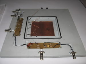
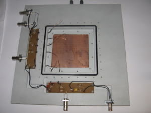
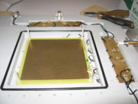
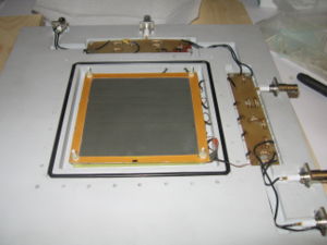
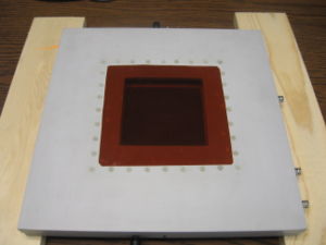
TGEMS : defined as GEM detector which use thick PCboard (0.4 mm thick) size GEM preamplifiers with hole diameters between 0.5 and 1 mm.
PCboard spacing = 1.5 - 2 mm.
TGEM Detector HV setting
[2]Media:Development_of_Tracking_Detectors_with_industrially_produced_GEM_Foils.pdf
is between ~[300V, 600V] for and for it is [200V, 370V];
voltage is ~[2900V, 5800V] ([1950V, 4000V]) for ().
Descriminated signals
HV setting
| Cathode HV (Volts) | First THGEM foil(Volts) | Second THGEM foil(Volts) | Third THGEM foil(Volts) | Third THGEM foil current A |
| 3000 | 1756 | 1657 | 1652 | 1273 |
Descriminator setup
I used 2 timing amps to integrate the signal and amplify more then the basic GEM.
The following setttings were
| Parameter | Dial setting</math>A |
| Timing Amp1 | 20 |
| Timing Amp1 Integration | 50 ns |
| Timing Amp2 | 4 |
| Timing Amp2 Integration | 20 ns |
| CFD Threshold | 5.22 |
| CFD Threshold ULD | 5.28 |
| CFD Threshold LLD | 3.04 |
