Difference between revisions of "JLAB PLX LVDS"
Jump to navigation
Jump to search
| Line 19: | Line 19: | ||
How to use Input register | How to use Input register | ||
| + | |||
| + | |||
| + | -> s3610Status | ||
| + | |||
| + | STATUS for SIS3610 id 0 at base address 0x91003800 | ||
| + | ------------------------------------------------ | ||
| + | Interrupts Enabled - Mode = 0 (0:RORA 1:ROAK) | ||
| + | VME Interrupt Level: 5 Vector: 0xe0 | ||
| + | Sources Enabled: 0x1 Sources Valid: 0x0 | ||
| + | |||
| + | MODULE ID register = 0x36101de0 | ||
| + | |||
| + | STATUS register = 0x00110000 | ||
| + | User Led Enabled : 0 | ||
| + | User Output Status : 0x0 | ||
| + | Flip-Flops Enabled : 0x1 | ||
| + | Latch Strobe Status: 0x0 | ||
| + | |||
| + | Direct Output Register = 0x0000 | ||
| + | Direct Input Register = 0x79fe | ||
| + | Latched Input Register = 0x79fe | ||
| + | value = 35 = 0x23 = '#' | ||
[http://wiki.iac.isu.edu/index.php/VME_modules Go back] | [http://wiki.iac.isu.edu/index.php/VME_modules Go back] | ||
[[VME_modules]] Go back | [[VME_modules]] Go back | ||
Revision as of 22:25, 17 March 2009
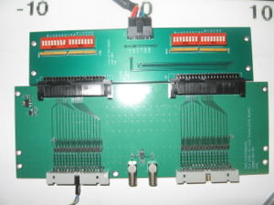
A VME Modules designed by Ed Jastrzembski at JLAB
Description:
This PLX board will be built on a Flex I/O format that Ed Jastrzembski developed many years ago. The VME (back end) manages the interface to the bus, and controls two front end 'ports' that can be input or output units.
3/17/09
How to use Input register
-> s3610Status
STATUS for SIS3610 id 0 at base address 0x91003800
------------------------------------------------
Interrupts Enabled  - Mode = 0  (0:RORA 1:ROAK)
VME Interrupt Level: 5   Vector: 0xe0
Sources Enabled: 0x1  Sources Valid: 0x0
MODULE ID register = 0x36101de0
 STATUS      register = 0x00110000
     User Led   Enabled : 0
     User Output Status : 0x0
     Flip-Flops Enabled : 0x1
     Latch Strobe Status: 0x0
 Direct Output Register = 0x0000
 Direct Input Register  = 0x79fe
 Latched Input Register = 0x79fe
value = 35 = 0x23 = '#'
Go back VME_modules Go back


