Difference between revisions of "Kalyan 23 May 08 2.1"
| Line 1: | Line 1: | ||
| − | ==3 inch Dia, 0.1 inch thk carbon rod== | + | ==3 inch Dia, 0.1 inch thk carbon rod carbon rod== |
The report generated by ANSYS is available: [[Image:Analysis_O_slice_3,0.1_1.pdf]] | The report generated by ANSYS is available: [[Image:Analysis_O_slice_3,0.1_1.pdf]] | ||
| Line 15: | Line 15: | ||
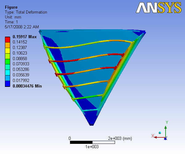
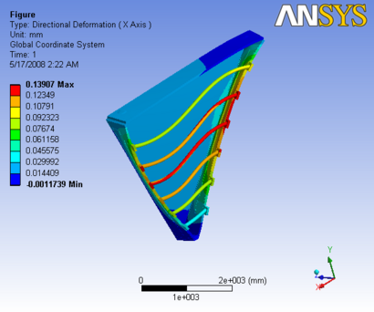
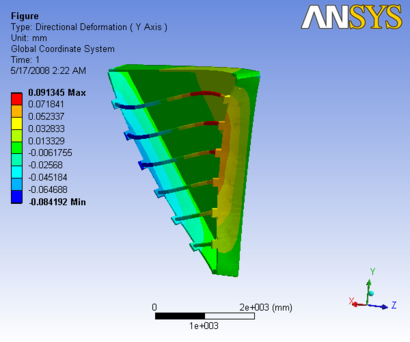
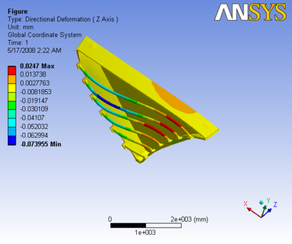
Figure 1: Images of Deflection for Sector 1 with 3 inch Diameter, 0.1 Inch thk carbon rods in D,X,Y,Z Directions respectively | Figure 1: Images of Deflection for Sector 1 with 3 inch Diameter, 0.1 Inch thk carbon rods in D,X,Y,Z Directions respectively | ||
| − | |||
| − | |||
==3.5 inch Dia, 0.1 Inch thk== | ==3.5 inch Dia, 0.1 Inch thk== | ||
Revision as of 10:38, 20 May 2008
3 inch Dia, 0.1 inch thk carbon rod carbon rod
The report generated by ANSYS is available: File:Analysis O slice 3,0.1 1.pdf
|
 |
 |
|
Figure 1: Images of Deflection for Sector 1 with 3 inch Diameter, 0.1 Inch thk carbon rods in D,X,Y,Z Directions respectively
3.5 inch Dia, 0.1 Inch thk
The report generated by ANSYS is available: File:Analysis O 3.5,0.1 slice 1.pdf
|
 |
 |
|
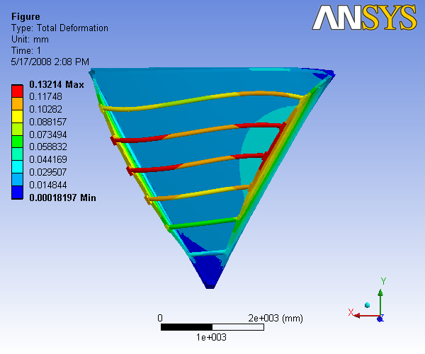
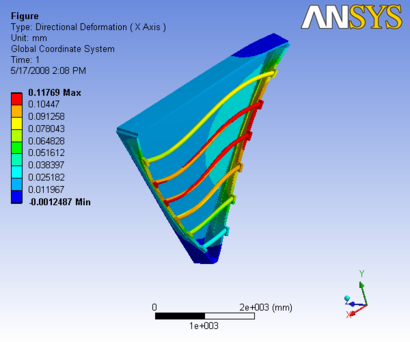
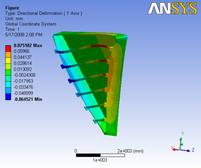
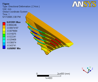
Figure 2: Images of Deflection for Sector 1 with 3.5 inch Diameter, 0.1 Inch thk carbon rods in D,X,Y,Z Directions respectively
3.5 inch Dia, 0.2 Inch thk
The report generated by ANSYS is available: File:Analysis O 3.5,0.2 slice 1.pdf
|
 |
 |
|
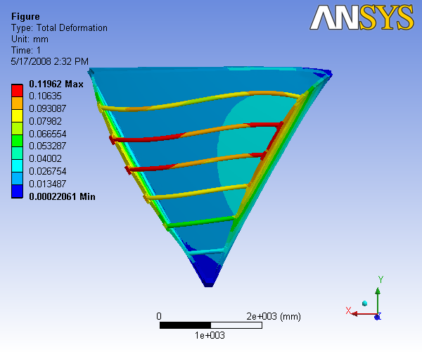
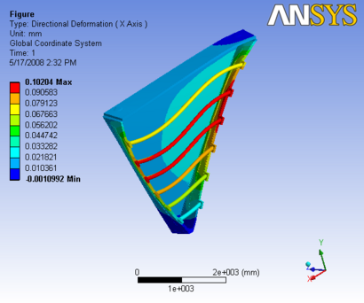
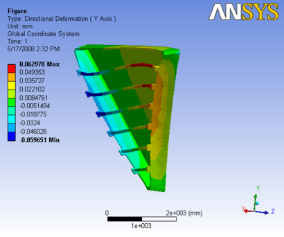
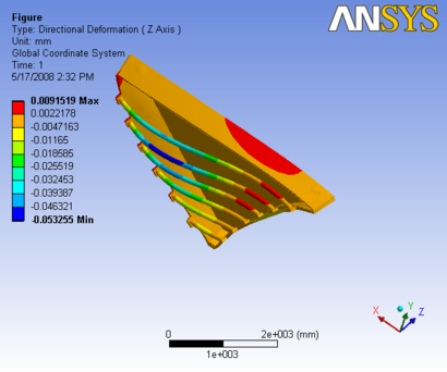
Figure 3: Images of Deflection for Sector 1 with 3.5 inch Diameter, 0.2 Inch thk carbon rods in D,X,Y,Z Directions respectively
3.5 inch Dia, 0.3 Inch thk
The report generated by ANSYS is available: File:Analysis O 3.5,0.3 slice 1.pdf
|
 |
 |
|
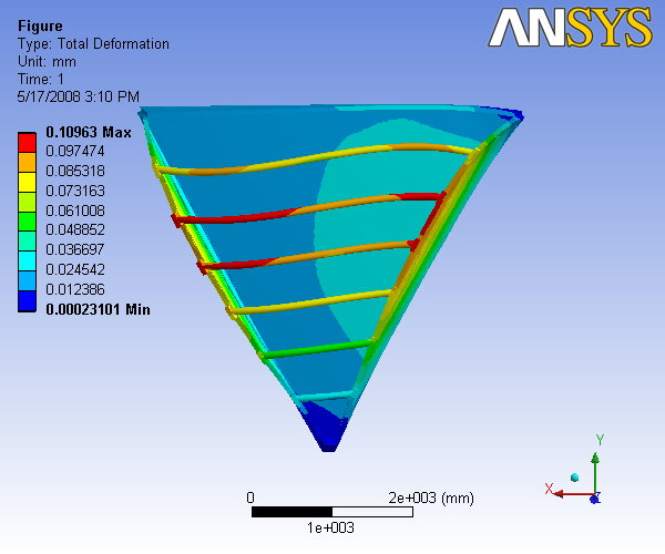
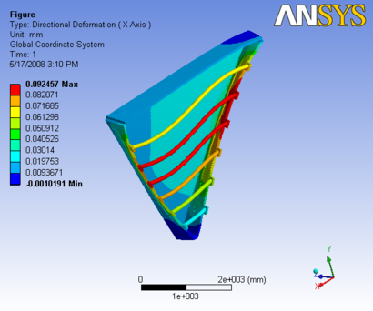
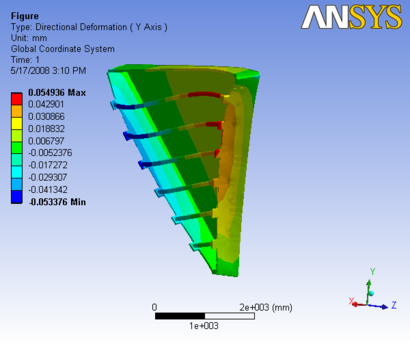
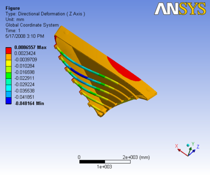
Figure 4: Images of Deflection for Sector 1 with 3.5 inch Diameter, 0.3 Inch thk carbon rods in D,X,Y,Z Directions respectively