Difference between revisions of "R3DC Report 2-08"
| Line 140: | Line 140: | ||
The load at which a carbon fiber rod will start to buckle is given by Euler's formula (insert Reference). The diagram below depicts the load configuration on the rod for this calculation. | The load at which a carbon fiber rod will start to buckle is given by Euler's formula (insert Reference). The diagram below depicts the load configuration on the rod for this calculation. | ||
| + | [[Image:EulersBucklingDiagramWequation.jpg]] | ||
| − | + | ||
| + | <math>F_{cr</math>} represent the critical force needed to cause the rod to begin to buckle. Young's Modulus (E) for a carbon fiber rod | ||
== Buckling FEA== | == Buckling FEA== | ||
Revision as of 03:29, 8 February 2008
Introduction
In this document we discuss the design of the Region 3 Drift Chambers (R3 DC) for the Hall-B 12-GeV upgrade (CLAS12). The objective for CLAS12 detectors is to achieve nearly full acceptance in the lab frame for the relativistic forward boosted final-state particles while maintaining a medium momentum resolution of 0.5 to 1% for a 5-GeV charged particle.
The six identical R3 DCs will be located 4.7 meters from the target and together the chambers will possess nearly full 2-π azimuthal coverage and will span from 5○ to 45○ in polar angle as measured from the direction of the electron beam. The central plane through the R3 DC will make an angle of 25○ with respect to the perpendicular to the beam. The toroidal coils will occlude {how many degrees?} in azimuth. The shadow of the toroidal coils will result in a [12-cm?] parallel gap between each R3 DC in which particles can’t have their trajectories reconstructed. This will provide the space for the readout boards, attendant electronics, cabling, etc. The active area for each R3 DC will then be [60 - ?] in azimuth,
The design of the R3 DC for CLAS12 is based on the successful hexagonal cell structure of the current CLAS R3 DC. Below we delineate the design criteria:
- Smaller cell size of 2.07 cm to accommodate a luminosity of 1035 cm-2 s-1 and maintain an accidental occupancy of less the 4% for high tracking efficiency..
- Sense wires will be increased to 30 um from the current 20 um diameter. This means that the wire will require a higher tension to offset droop and electrostatic forces.
- All wires in each superlayer will lie in a plane instead of on a cylindrical surface. The staggered by one half cell or “brick wall pattern” of the hexagonal cells will be maintained for each successive layer.
- To enhance the azimuthal (φ) resolution, each superlayer will be +/- stereo, i.e. the pitch will be +6○ in the six layers of the first superlayer and the pitch will be -6○ for the second superlayer array of six wire planes. The current R3 DC has 0○ and 6○ pitch respectively for the two superlayers.
- There will be a total of 4928 wires of which 1344 (check this) will be sense wires.
- Endplates will be secured into rigid frames. The endplates will be oriented 60○ with respect to one another. Into each endplate will be precisely drilled holes with tolerance of better than 100 um. Into these hole will be placed the feedthrough assemblies for precisely positioning the sense, field, and guard wires. The expected overall position accuracy will be 250 um per layer, with a wire location accuracy of 200 um.
- The deflection along the length of the endplates may not exceed 50 um.
- The R3 DCs will be supported from only two points at the outer backplane. This makes the R3 DCs self supporting.
- The nose plate for each R3 DC will be positioned onto a precision support hexagonal ring for aligning all R3 DCs with respect to the surveyed Hall B coordinate system.
The mechanical engineering aspects of the R3 DC is discussed below in light of the above design criteria. We present a two dimensional Finite Element Analysis. The three-dimensional FEA is currently under study
R3 Description
Geometry
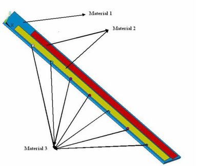
Material Specifications
| Material | Youngs Modulus | Density |
| MPa | ||
| Polyeurethane Foam FR-3700 | 140 | 240 |
| Hexacell with holes | ||
| Carbon Fiber Rods | 210 | 580 |
Specific part Drawings
Endplate Deflection
Point Load Deflection
A simple calculation based on the definition of Young's modulus can yield an order of magnitude level estimate for the deflection of an endplate made from Aluminum. According to the definition of Young's modulus
where
- Young's Modulus for Aluminum
- point force/load
- width of the endplate
- deflection of endplate due to point force
- length of the endplate
- thickness of the endplate
A deflection of 14 mm is expected for a 5 cm thick Aluminum endplate, after solving the above equation for and inserting the given values. If a 5 cm thick stainless steel endplate were used, the deflection would drop by almost factor of 3 from 14 mm to 5 mm due to the linear dependence of the deflection on Young's Modulus. The previous work of Kevin Folkman led to a similar conclusion.
Distributed Load Deflection
The endplate deflection calculation was redone assuming a more realistic case in which the load is distributed evenly along the endplate. The tension of the wires on the endplate was divided into three regions; W1,W2, and W3. As shown in the Figure below, the load W3 corresponds to a region along the endplate in which wires from both super layers are creating a load on the endplate. Loads W1 and W2 represent regions in which only 1 super layer is causing a load. The endplate is "simply" supported in order to calculate the deflection. The "simple" support has a point support on the left side in which the endplate may rotate but not translate (move left or right). The right hand side of the plate is supported such that the endplate can both rotate and translate. The figure below labels the loads as well as distances over which the loads are applied on the end plate. A wire tension of 340 lbs is decomposed into its components due to the angle made by the wire on the endplate.
| Label | value |
| a | 99.02 mm |
| b | 96.22 mm |
| c | 4025.88 mm |
| d | 335.17 mm |
| e | 273.88 mm |
| 0.255 N/mm | |
| 0.59 N/mm | |
| 0.335 N/mm |
Assumptions
The following assumption were made in the hand calculation:
- The end plate is made of homogenous uniform elastic material with a Young's Modulus of E=210 x 103 N/mm2 (Stainless Steel).
- The horizontal component of the loading is completely neglected.
- The deflection in the x-direction is negligible.
- The end plate is rectangular in shape with a width of 526 mm and thickness of 50.8 mm resulting moment of inertia (I) =5746.4 .
- The loading provided by wire tensions are equivalent to a uniformly distributed load.
- The maximum deflection occurs along the length which is represented by in the diagram.
- The loading applied is under the elastic limit of the material.
- The effects of the endplate weight are ignored.
The moments experience along the endplate are shown below for each of the 5 distances.
where represents the .
The deflection in the y-direction is governed by the equation
where represents Young's Modulus and is the Area Momentum of Inertia. The Area Moment of Inertis (I_A) is defined as the second moment of an area about a given axis.
- Area moment of inertia about the x-axis.
The mass moment of Inertia is defined as
If we assume that the largest amount of deflection occurs in region c, then we may integrate the above 2nd order differential equation once and determine the critical point which represents the point of maximum deflection ( contra flexure).
- =
- constant of integration
Setting to zero and solving for x give the result that x = 1654.96 mm. In other words, the maximum deflection occurs 1654.96 mm from region of the endplate or 1 mm from the right hand side of the endplate.
Integrating the equation a 2nd time will result in an equation for the amount of the deflection. Substituting the value of x above results in a predicted deflection in the Y deflection of 2.2 mm after dividing by . The predicted deflection is at least a factor of 2 smaller than a point load when the load is distributed along the length of the end plate.
Distributed load FEA
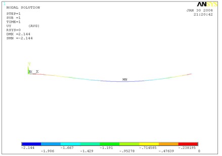
A Finite Element Analysis (FEA) was performed using the computer software ANSYS. The maximum deflection observed was 2.144 mm as shown in the Figure below and differs from the hand calculation by only 3%. In addition to validating the FEA analysis with hand calculations, the above results also reveal the challenge of reducing the endplate deflection using stiffer materials due to an essentially linear dependence of the deflection to Young's Modulus. The cubic dependence of the deflection on the thickness of the endplate, however, can be used to reach the minimum endplate deflection criteria of 50 instead of using stiffer material. Increasing the endplate thickness comes at the cost of increasing the end plate mass. As a result, composite materials were considered in order to minimize weight. The performance of these composite materials is shown in the 3-D model section of this report.
Carbon Rod Buckling
Compression
Buckling Load Threshold
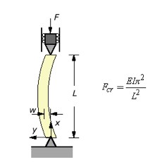
The load at which a carbon fiber rod will start to buckle is given by Euler's formula (insert Reference). The diagram below depicts the load configuration on the rod for this calculation.
} represent the critical force needed to cause the rod to begin to buckle. Young's Modulus (E) for a carbon fiber rod


