Difference between revisions of "MCNP Sim of Jack Converter"
Jump to navigation
Jump to search
| Line 15: | Line 15: | ||
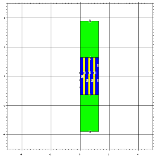
[[File:JackSimGeomFront.png | 300px | thumb| Side profile of converter. Distances re in cm. There are thin (0.001 inch) titanium plates on the far left and far right of the model, but they but the are too small to be seen.]] | [[File:JackSimGeomFront.png | 300px | thumb| Side profile of converter. Distances re in cm. There are thin (0.001 inch) titanium plates on the far left and far right of the model, but they but the are too small to be seen.]] | ||
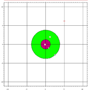
[[File:JackSimGeomProfile.png | 300 px|thumb| Front view of convertor. Distances are in cm. ]] | [[File:JackSimGeomProfile.png | 300 px|thumb| Front view of convertor. Distances are in cm. ]] | ||
| − | |||
| − | |||
==Assumptions== | ==Assumptions== | ||
| + | The beam spot size was given a diameter of 0.5 cm based off of a burn mark on a converter that got hot during irradiation. | ||
Revision as of 22:39, 30 August 2018
Simulation inputs
Geometry
Materials
Green: Stainless steel
Pink: Titanium
Blue: H2O
Yellow: Tungsten
Assumptions
The beam spot size was given a diameter of 0.5 cm based off of a burn mark on a converter that got hot during irradiation.

