Difference between revisions of "LB January Flux Simulations"
| Line 22: | Line 22: | ||
/run/beamOn 50000 | /run/beamOn 50000 | ||
| + | |||
| + | The dimensions of the pieces of interest are: | ||
| + | |||
| + | Se Pellet: 0.25cm radius | ||
| + | Nickel Foil: 6cm in x, 2cm in y | ||
A picture of the setup is shown below: | A picture of the setup is shown below: | ||
| Line 31: | Line 36: | ||
| + | |||
| + | The first plot shown is simply the ratio of the number of particles that passed through the target. The second plot the number of particles passing through each target weighted by the cross sectional area of the target. | ||
There were some strange issues while performing this simulation. The first issue that stuck out was that when trying to create a G4Orb for the selenium pellet, the program would compile, but the orb would not be present in the visualizer and furthermore would not have particles written to the outfile. A similar issue happened when trying to curve the nickel foil and the aluminum cylinder. If the nickel foil and the aluminum cylinder were curved, perhaps the number of particles passing through them would be lower which would raise the ratio of the number of particles. | There were some strange issues while performing this simulation. The first issue that stuck out was that when trying to create a G4Orb for the selenium pellet, the program would compile, but the orb would not be present in the visualizer and furthermore would not have particles written to the outfile. A similar issue happened when trying to curve the nickel foil and the aluminum cylinder. If the nickel foil and the aluminum cylinder were curved, perhaps the number of particles passing through them would be lower which would raise the ratio of the number of particles. | ||
Revision as of 17:45, 18 January 2018
Simulations were run using geant4 to try and see if the ratio of the flux between the nickel foil and the inner selenium pellet would explain why the ratios of the rates are not correct. A general particle source was used to fire electrons in a beam at a titanium beam window, which then proceeds to an aluminum/tungsten radiator. After that the particles will encounter a nickel foil followed by an aluminum sheet and finally a selenium pellet that is -0.75cm off of the beam axis (to try and replicate the location of the foil relative to the selenium pellet). The run.mac file is shown below
/gps/particle e-
/gps/position 0 0 -5 m
/gps/pos/type Plane
/gps/pos/shape Circle
/gps/pos/radius 0.5 cm
/tracking/verbose 2
/gps/direction 0 0 1
/gps/verbose 2
/gps/pos/sigma_r 0.5 cm
/gps/energy 32 MeV
/run/beamOn 50000
The dimensions of the pieces of interest are:
Se Pellet: 0.25cm radius Nickel Foil: 6cm in x, 2cm in y
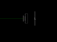
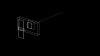
A picture of the setup is shown below:
Below is a plot of the ratio of the number of particles in the selenium divided by the number of particles in the Nickel foil
The first plot shown is simply the ratio of the number of particles that passed through the target. The second plot the number of particles passing through each target weighted by the cross sectional area of the target.
There were some strange issues while performing this simulation. The first issue that stuck out was that when trying to create a G4Orb for the selenium pellet, the program would compile, but the orb would not be present in the visualizer and furthermore would not have particles written to the outfile. A similar issue happened when trying to curve the nickel foil and the aluminum cylinder. If the nickel foil and the aluminum cylinder were curved, perhaps the number of particles passing through them would be lower which would raise the ratio of the number of particles.

