Difference between revisions of "Reproducibility Shots July 2017"
Jump to navigation
Jump to search
| Line 5: | Line 5: | ||
I have overlaid X and Y profiles as well as created 3D renderings of the beam profile for the front and back sets of OSLs. Note that it is flat due to the distance at which the board was placed from the end of the accelerator. | I have overlaid X and Y profiles as well as created 3D renderings of the beam profile for the front and back sets of OSLs. Note that it is flat due to the distance at which the board was placed from the end of the accelerator. | ||
| − | Diode diameter:2" | + | Diode diameter: 2" |
| − | gap: 1.5" | + | Diode gap: 1.5" |
Al vacuum plate thickness: 5/8" | Al vacuum plate thickness: 5/8" | ||
| Line 13: | Line 13: | ||
Ta thickness: 0.020" | Ta thickness: 0.020" | ||
| − | Distance | + | Distance to Board: 109 cm |
| − | |||
| − | |||
[[File:Shot 1 Front Jul2017.png|400px|thumb|left|*Unknown calibration on OSL reader]] | [[File:Shot 1 Front Jul2017.png|400px|thumb|left|*Unknown calibration on OSL reader]] | ||
Revision as of 20:03, 26 July 2017
Shot 169
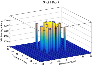
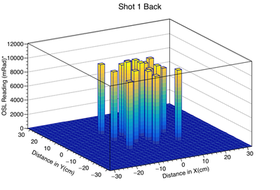
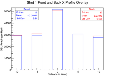
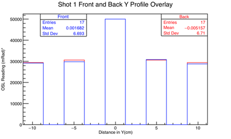
In this experiment, I picked 17 different points on my OSL board to test agreement between two OSLs at the same physical location for the same shot from TriMeV.
I have overlaid X and Y profiles as well as created 3D renderings of the beam profile for the front and back sets of OSLs. Note that it is flat due to the distance at which the board was placed from the end of the accelerator.
Diode diameter: 2"
Diode gap: 1.5"
Al vacuum plate thickness: 5/8"
Ta thickness: 0.020"
Distance to Board: 109 cm


