Difference between revisions of "Wire angle correspondance"
(Created page with "=Determining wire-theta correspondance= To associate the hits with the Moller scattering angle theta, the occupancy plots of the drift chamber hits by means of wire numbers and l…") |
|||
| Line 114: | Line 114: | ||
==Super Layer 1:Layer 6== | ==Super Layer 1:Layer 6== | ||
| + | For a hit at layer 2, wire 1 we find the corresponding angle theta in the lab frame to be 5.30 degrees | ||
<center>[[File:Superlayer1_layer6_wire1.png]]</center> | <center>[[File:Superlayer1_layer6_wire1.png]]</center> | ||
| + | Examing a hit at layer 2, wire 112 we find the corresponding angle theta in the lab frame to be 40.61 degrees | ||
| + | <center>[[File:Superlayer1_layer6_wire112.png]]</center> | ||
| + | |||
| + | |||
| + | This sets the lower limit: | ||
| + | |||
| + | <center><math>\frac{5.30^{\circ}}{1}\frac{\pi\ radians}{180^{\circ}}=.09250245\ radians\approx 0.025\ radians</math></center> | ||
| − | <center> | + | This sets the upper limit: |
| + | |||
| + | <center><math>\frac{40.61^{\circ}}{1}\frac{\pi\ radians}{180^{\circ}}=.7087782\ radians\approx 0.709\ radians</math></center> | ||
| + | |||
| + | Taking the difference, | ||
| + | |||
| + | <center><math>.716457657944-.0872664626\approx\ .616\ radians</math></center> | ||
| + | |||
| + | |||
| + | Dividing by 112, we find | ||
| + | |||
| + | <center><math>\frac{.61627575}{112}=.00550246\ radians\approx\ 0.00550\ radians</math></center> | ||
==Superlayer 2:Layer 1== | ==Superlayer 2:Layer 1== | ||
Revision as of 20:14, 16 November 2016
Determining wire-theta correspondance
To associate the hits with the Moller scattering angle theta, the occupancy plots of the drift chamber hits by means of wire numbers and layer must be translated using the physical constraints of the detector. Using the data released for the DC:
DC: Drift Chambers(specs)
This gives the detector with a working range of 5 to 40 degrees in Theta for the lab frame, with a resolution of 1m radian.
This sets the lower limit:
This sets the upper limit:
Taking the difference,
Dividing by 112, we find
CED Verification
Using CED to verify the angle and wire correlation,
Super Layer 1:Layer 1
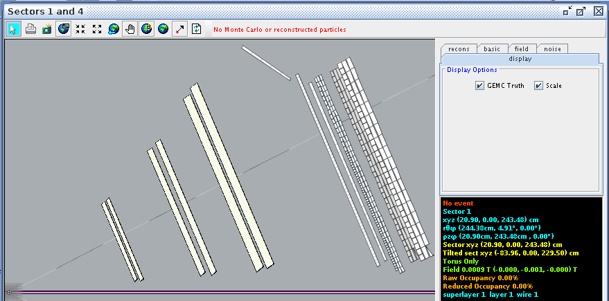
For a hit at layer 1, wire 1 we find the corresponding angle theta in the lab frame to be 4.91 degrees
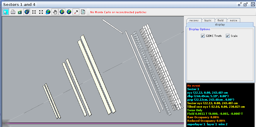
For a hit at layer 1, wire 2 we find the corresponding angle theta in the lab frame to be 5.19 degrees
Finding the difference between the two wires,
Examing a hit at layer 1, wire 112 we find the corresponding angle theta in the lab frame to be 40.70 degrees
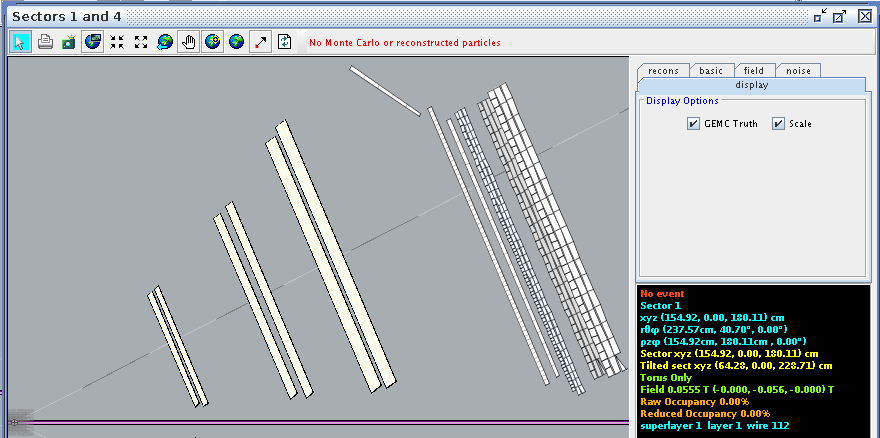
This sets the lower limit:
This sets the upper limit:
Taking the difference,
Dividing by 112, we find
Noting the difference from the spacing for a single cell, to the entire detector layer
An uncertainty of this magnitude in radians corresponds to an angular uncertainty of
Testing this for a random angle, 78 degrees we find
Adding this to the starting angle of 4.91 degrees
Comparing this to CED at wire 78
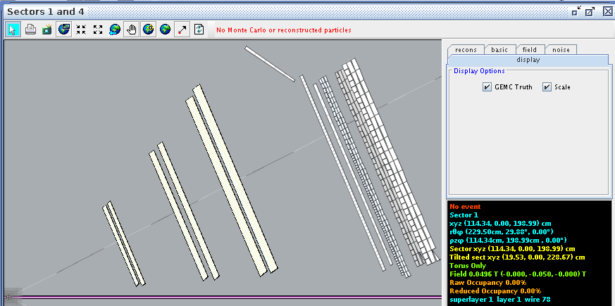
Super Layer 1:Layer 2
For a hit at layer 2, wire 1 we find the corresponding angle theta in the lab frame to be 5.00 degrees
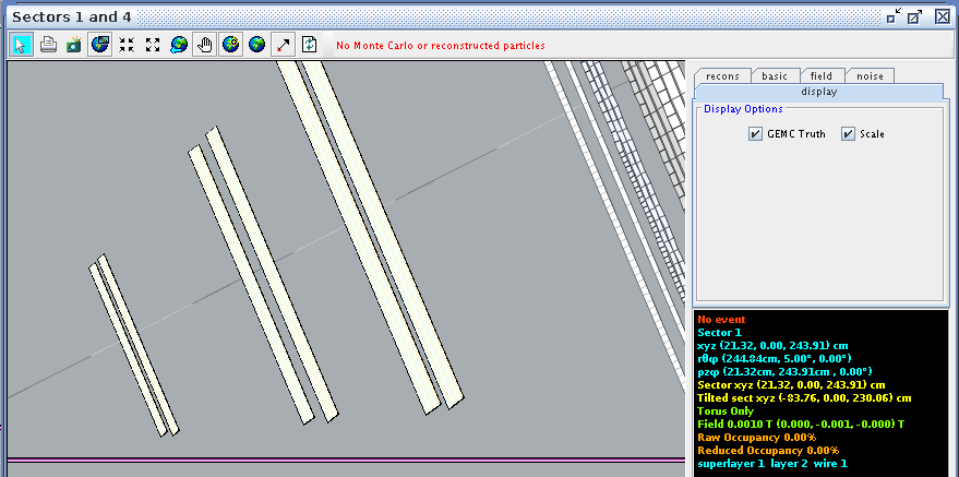
Examing a hit at layer 2, wire 112 we find the corresponding angle theta in the lab frame to be 41.05 degrees
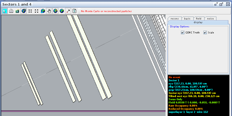
This sets the lower limit:
This sets the upper limit:
Taking the difference,
Dividing by 112, we find
Super Layer 1:Layer 6
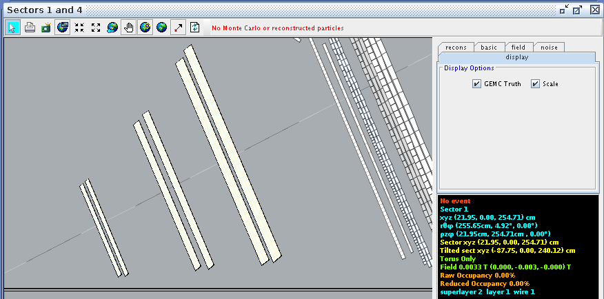
For a hit at layer 2, wire 1 we find the corresponding angle theta in the lab frame to be 5.30 degrees
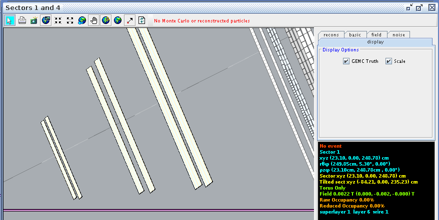
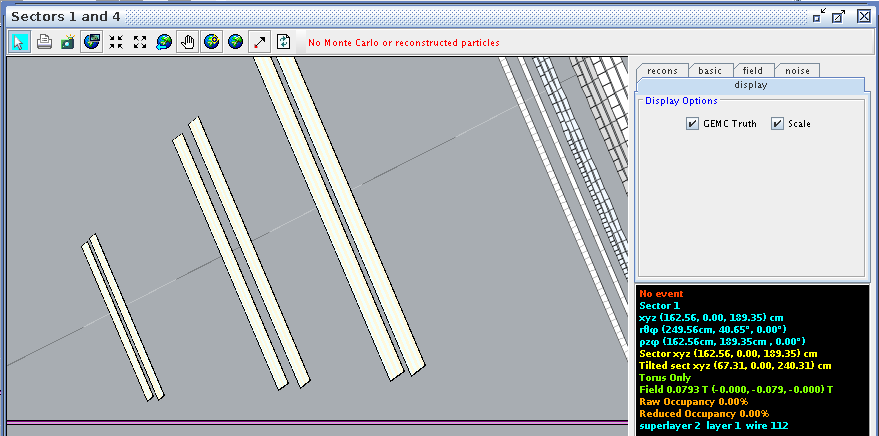
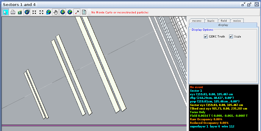
Examing a hit at layer 2, wire 112 we find the corresponding angle theta in the lab frame to be 40.61 degrees
This sets the lower limit:
This sets the upper limit:
Taking the difference,
Dividing by 112, we find
Superlayer 2:Layer 1
