Difference between revisions of "Niowave Report 11-30-2015"
| Line 8: | Line 8: | ||
One method to produce positrons relies on the creation of positron-electron pairs from the bremsstrahlung photons that are produced when electrons traverse a material with a high atomic number (Z). While thicker material encourages the production of these photons, the increased thickness will also cause the produced positrons to annihilate within the material before they can escape. As a result, there is an optimal thickness which will balance the two processes and maximize positron production. A simulation was performed to determine the optimal thickness using a 10 MeV electron beam with a 1cm radius uniform cylindrical spatial distribution impinging a windowless LBE target. The target thickness was changed to determine the optimal thickness for positron emmission from the downstream surface of the LBE target. The simulation was performed by two separate investigators using separate simulation packages. The results, shown below, indicate that a LBE target thickness of about 2 mm will produce about two positrons for every thousand electrons impinging the LBE target. | One method to produce positrons relies on the creation of positron-electron pairs from the bremsstrahlung photons that are produced when electrons traverse a material with a high atomic number (Z). While thicker material encourages the production of these photons, the increased thickness will also cause the produced positrons to annihilate within the material before they can escape. As a result, there is an optimal thickness which will balance the two processes and maximize positron production. A simulation was performed to determine the optimal thickness using a 10 MeV electron beam with a 1cm radius uniform cylindrical spatial distribution impinging a windowless LBE target. The target thickness was changed to determine the optimal thickness for positron emmission from the downstream surface of the LBE target. The simulation was performed by two separate investigators using separate simulation packages. The results, shown below, indicate that a LBE target thickness of about 2 mm will produce about two positrons for every thousand electrons impinging the LBE target. | ||
| − | |||
{| border="1" | {| border="1" | ||
Revision as of 01:06, 1 December 2015
Overview
This report investigates the impact of target thickness and the use of an external solenoid for the production of positrons using a 10 MeV electron beam. An electron beam energy of 10 MeV is chosen as a compromise between maximizing the production of bremsstrahlung photons and minimizing the production of neutrons that occur when an MeV energy electron beam interacts with a dense metal. A converter target of liquid Lead-Bismuth Eutectic (LBE) is chosen with a concentration of 44.5% lead and 55.5% bismuth in order to provide a high atomic number (Z) material to increase bremsstrahlung production. The liquid LBE target will also more readily absorb the heat deposited when the material is traversed by an MeV electron beam. This work used the simulation package GEANT4 to predict the impact of target thickness and the use of a solenoidal magnetic field on positron production efficiency as well as the amount of energy that will be deposited by scattered electrons in the apparatus when using a 3.48 cm diameter beam pipe.
Target optimization
Optimal Thickness
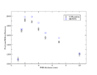
One method to produce positrons relies on the creation of positron-electron pairs from the bremsstrahlung photons that are produced when electrons traverse a material with a high atomic number (Z). While thicker material encourages the production of these photons, the increased thickness will also cause the produced positrons to annihilate within the material before they can escape. As a result, there is an optimal thickness which will balance the two processes and maximize positron production. A simulation was performed to determine the optimal thickness using a 10 MeV electron beam with a 1cm radius uniform cylindrical spatial distribution impinging a windowless LBE target. The target thickness was changed to determine the optimal thickness for positron emmission from the downstream surface of the LBE target. The simulation was performed by two separate investigators using separate simulation packages. The results, shown below, indicate that a LBE target thickness of about 2 mm will produce about two positrons for every thousand electrons impinging the LBE target.
|
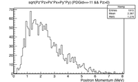
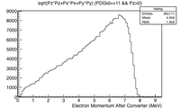
The momentum distribution of positrons escaping the downstream side of the LBE target is shown below along with the momentum distribution of electrons that traverse the LBE target. Positrons leaving the downstream side of the target are predicted to have a mean momentum of 2.4 MeV whereas the electrons that penetrate the LBE target will have lost approximately 3 MeV. Most of the positrons have a momentum between one and three MeV. A system to transport these electrons would need to cover this momentum range to avoid appreciable loss. A solenoidal magnetic field was chosen that surrounds the LBE target. A description of the solenoid is given below.
|
Solenoid Description
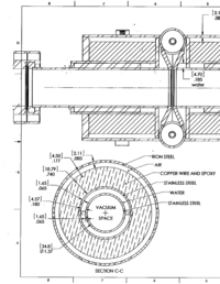
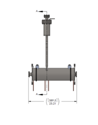
A solenoidal magnetic field is created around the beam pipe using two wire loops. One loop, 20 cm long, is placed upstream of the LBE target and a second , 40 cm, loop is placed downstream. Water flows between the beam pipe and the solenoid surrounding the beam pipe to provide cooling. The figures below illustrate the solenoid design and the table provides the dimensions of several elements.
| Element | dimension |
| Inner beam pipe radius | 1.74 cm |
| Inner beam pipe thickness | 0.165 cm |
| Water jacket thickness | 0.457 cm |
| Outer beam pipe radius | 2.362 cm |
| Outer beam pipe thickness | 0.165 cm |
| Solenoid inner radius | 2.527 cm |
| Solenoid outer radius | 4.406 cm |
Optimal Solenoidal Field
The use of solenoid magnetic field for collecting positrons emitted on the downstream side of the LBE target was investigated. A solenoidal magnetic field will cause both electrons and positrons to spiral along the beam pipe in a helical path. Less magnetic field strength is needed to collect the lower momentum positrons relative to the electrons. As the strength of the magnetic field increases, electrons will begin to spiral down the beam pipe instead of intersecting the beam pipe and depositing energy. The amount of energy deposited by these electrons is the dominant source of beam pipe heating. The magnitude of the magnetic field was changed to determine the impact on beam pipe heating and the transportation of positrons out of the solenoidal field. A set of 0.25 mm thick stainless steel windows were added to the 2mm thick LBE target for this simulation.
Beam Pipe heating
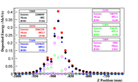
The energy deposited by electrons scattered into a 1.65 mm thick stainless steel beam pipe from the LBE target as a function of a uniform solenoidal magnetic field was investigated for a 3.48 diameter stainless steel beam pipe. The simulation program GEANT4 was used to determine the amount of energy an electron lost in the stainless steel beam pipe. The beam pipe surface was divided into unit squares that were a centimeter in length and the energy deposited by a sample of 5 million electrons was summed for each unit square. The left side figure below shows a predicted peak energy deposition of 0.35 MeV/cm^2 in the 1.65 mm thick stainless steel beam pipe per 10 MeV electron impinging the 2 mm thick LBE target that has been sandwiched between two 0.25 mm thick stainless steel windows.
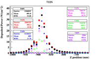
The energy deposited in the beam pipe can be converted to an average heat load if a average beam current is assumed. Under the assumption of a 1mA (10^-3 C/s) average beam current, the deposited energy (E_{dep}) per cm^2 per electron can be converted to the deposited power (P) per area using the equation
In other words, the energy deposited in units of keV/cm^2/e by a 1 mA electron beam is equivalent to a heat load in the units of Watts per cm^2.
Based on this observation the peak heat load, as shown in the figure below on the right, for a 1 mA electron beam is 3.5 W/cm^2. The electrons will begin to intersect a 3.48 diameter beam pipe less when the solenoidal magnetic field strength increases beyond one Tesla. A solenoidal field between two and four Tesla would substantially reduce the electron heat load on the beam pipe and place the positrons in a tight helical orbit for transportation.
add units to the histograms below
 |
|
Positron Production for several Solenoidal fields and beam pipe radii
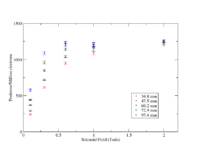
The positron collection efficiency was investigated for several solenoidal magnetic field strengths and beam pipe radii to determine the impact of using a solenoidal field strength that was less than one Tesla. The figure below shows the number of positrons that exit the solenoid for every million electrons that impinge a 2mm thick LBE target sandwiched between 0.25 mm thick stainless steel windows. If the solenoids field strength was limited to a maximum of 0.3 Tesla, then a 97.5 mm diameter beam pipe would have the same positron transport efficiency as a 1.0 Tesla field and a 34.8mm diameter beam pipe. Otherwise, the positron tranport efficiency can increase by a factor of two when using a 34.8 mm diamter beam pipe if the solenoidal field strength is increased from 0.3 Tesla to 1.0 Tesla.
Fix the beam pipe diameter captions from 39.4 to 34.8 mm
|
Summary
A simulation was performed to determine the optimal thickness of LBE for positron production and the impact of a solenoidal field on the transportation of charged particles downstream of the target. The simulation predicts that a 10 MeV electron incident on a 2 mm thick LBE target will maximize positron production at a rate of 2 positrons per thousand, 10 MeV incident electrons. If a 40 cm long solenoid is placed downstream of the target, then at least an average of 1.5 positrons will exit the solenoid per thousand, 10 MeV incident electrons if the field strength is 1 Tesla. This production rate is predicted to drop to and average of 0.6 positrons per thousand, 10 MeV electrons if the field is reduced to 0.3 Tesla and a 34.8 mm diameter beam pipe is used.
