Difference between revisions of "Niowave Report 11-30-2015"
Jump to navigation
Jump to search
| Line 20: | Line 20: | ||
<math>\left( \frac{\mbox{keV}}{\mbox{cm}^2 \mbox{e}^-}\right) = \left( \frac{\mbox{W} }{\mbox{cm}^2 } \right )</math> | <math>\left( \frac{\mbox{keV}}{\mbox{cm}^2 \mbox{e}^-}\right) = \left( \frac{\mbox{W} }{\mbox{cm}^2 } \right )</math> | ||
| − | |||
| − | |||
| − | |||
| − | |||
| − | |||
| − | |||
| − | |||
| − | |||
| − | |||
| − | |||
| − | |||
| − | |||
| − | |||
| − | |||
| − | |||
| − | |||
| − | |||
| − | |||
| − | |||
Revision as of 00:11, 28 November 2015
Target optimization
Optimal Thickness
Optimal Solenoidal Field
Beam Pipe heating
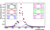
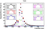
The energy deposited by electrons scattered into a 3.48 diameter stainless steel beam pipe (1.65 mm thick) from a PbBi target as a function of a uniform Solenoidal magnetic field.
The histogram is binned in 100 (10 cm) bin widths. The surface area becomes
To convert From Mev/ e- to kW/cm^2 assuming a current of 1mA (10^-3 C/s) you
 |

|
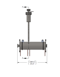
Solenoid Descritpion
A 10 MeV electron beam with a radius of 0.5 cm was incident on a 2 mm thick PbBi target. The target is positioned at Z = -901 mm.
