Difference between revisions of "PePPO 02222012"
| (5 intermediate revisions by 2 users not shown) | |||
| Line 4: | Line 4: | ||
https://cebaf.jlab.org/atlis/task/12074 | https://cebaf.jlab.org/atlis/task/12074 | ||
| + | |||
| + | = JLab Wiki = | ||
| + | |||
| + | https://positron.jlab.org/wiki/index.php/02222012_AnnihCntr_TestPlan | ||
=Accelerator Configuration= | =Accelerator Configuration= | ||
| Line 226: | Line 230: | ||
Dead time = L1A/L1 | Dead time = L1A/L1 | ||
| + | Erica Said | ||
| + | L1 or Level 1 is the incoming trigger. In this case is the detector signal (or the AND, when there is a coincidende, of the 2 detector signals) used as a start. | ||
| + | The L1A or Level 1 Accept is the signal coming from the VME CPU that tells to the rest of the electronics that it can read and accept trigger, because it is not busy processing the previous data. | ||
| + | |||
| + | My understand is: L1 is incoming triggers. L1A are those L1 that is accepeted (or executed). | ||
| + | |||
| + | So, L1A/L1 should be the live time. | ||
| − | <math>\frac{\frac{L1A}{L1 \ | + | <math>\frac{\left . \frac{L1A}{L1}\right |_{Beam on}}{\left .\frac{L1A}{L1} \right |_{Beam off}} = \frac{0.03}{0.17} = \frac{1}{6} \Rightarrow </math> mutiply the beam on data by a factor of 6 and leave the beam off data alone |
| − | |||
| − | |||
{| border="1" |cellpadding="20" cellspacing="0 | {| border="1" |cellpadding="20" cellspacing="0 | ||
Latest revision as of 04:48, 8 March 2012
- Below is a beam test plan for the PePPO annihilation counters.
ATLIS task #
https://cebaf.jlab.org/atlis/task/12074
JLab Wiki
https://positron.jlab.org/wiki/index.php/02222012_AnnihCntr_TestPlan
Accelerator Configuration
- Accelerator Settings
| beam energy | 6.8 MeV |
| Beam type: | Electron |
| I_average: | 0.3 nA |
| I_peak: | 0.05 A 0.006 duty factor |
| pulse width: | 10 s |
| Rate: | 60 Hz |
| PEPPO Spectrometer: | 151.3 A |
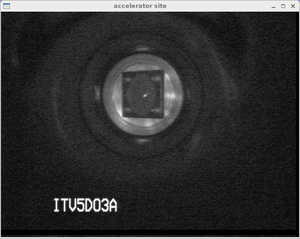
Observe Beam spot on ITV5D03A
Record an image of the beam spot size seen by the ChroMox viewscreen.
https://cebaf.jlab.org/elog/entry/1666618
Turn on Annihilation Counters
Step 1: Bring up MEDM slow controls screen (skip if PEPPO screen is already up)
Skip this step if MEDM is already available on your screen
Otherwise
ssh username@opsmdaq1
type the following command to start the MEDM screen
opsmenu
a screen appears with one button called "OPS Menu"
a submenu appears when you click on that button.
Select the "EDM" menu.
The Monticello GUI will appear
click on the Injector screen (left button") and select "PePPO overview" from the menu
Look for a menu item with the title associated with the annihilation counters
Step2: Set HV to Detectors
Set the value of the HV dac listed in the table below (0-5) which corresponds to the desired HV for Detector #1 or #2.
For example: If you set HV dac value to 2.4 for detector #1 then its HV will be set to 960 which should bring the 511 peak into range for the FADC.
| Signal channel | HV dac | HV (V) | |
| Detectors #1 | A1 | 2.4 | 960 |
| Detectors #2 | A2 | 3.0 | 1200 |
There is on/off button for HV PS on the control menu. After setting the above HV dac values, you need to turn it on, then you will notice the display column change with a read back value.
Set FADC threshold
Login to the IOC for the FADC (on 11/7/2011 the command "telnet iocmdaq1" worked)
When logged in to the ROC for the FADC you use the function below to set the FADC threshold
faSetThreshold(FA_SLOT,fADC_Threshold,0xffff);
On Aug of 2011 the following values worked
fADC_Theshold = 200
FA_SLOT=?
- reminder
- the processing mode function has the following syntax
faSetProcMode(FA_SLOT,1,280,250,3,6,1,0);
Setup CODA run configuration
If CODA is running select the run configuration
"Annih_Sample"
If CODA isn't running
go to the CODA Runcontrol GUI and check that the configuration is using "FADC"
if coda isn't running try use the information below to start it
Take Data
Log book entry
https://cebaf.jlab.org/elog/entry/1666585
https://cebaf.jlab.org/elog/entry/1666627
Target in
Check that the ChroMox target is in by observing a beam spot
Then start the DAQ and run for 15 minutes
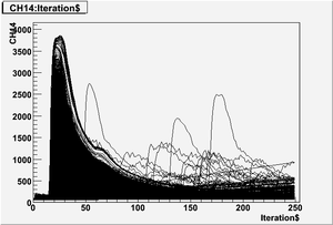
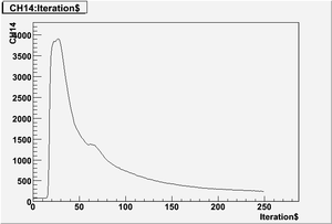
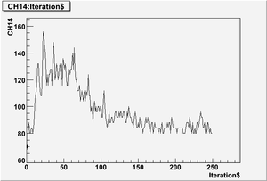
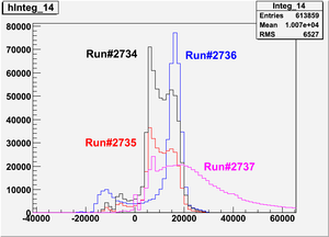
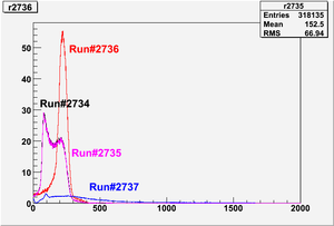
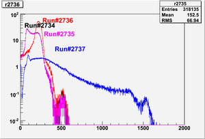
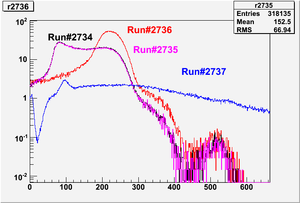
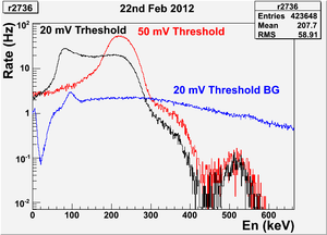
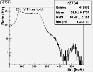
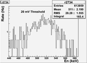
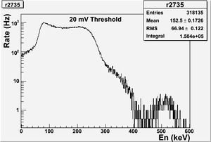
| Run# | run mode | Beam | Target | Trig at | Run Duration | VME discriminator Threshold (mV) | HV1 (setting/V) | HV2 (setting/V) | PL (setting/ns) | PTW (setting/ns) | Det1 connected to | Det2 connected to | Spectrum | 511 / Beam Current |
| 2734 | sample | on | In | det1 | 130 s | 20 | 2.4/960 | 3/1200 | 280/1120 | 250/1000 | FADC Chan#14 | Not connected | 300 px | 4.9 /0.3 nA = 16.33 Hz/nA 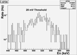
|
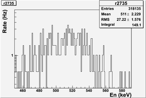
| 2735 | sample | on | In | det1 | 69 s | 20 | 2.4/960 | 3/1200 | 280/1120 | 250/1000 | FADC Chan#14 | Not connected | 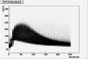 |
4.246 /0.3 nA = 14.15 Hz/nA 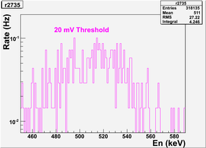
|
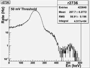
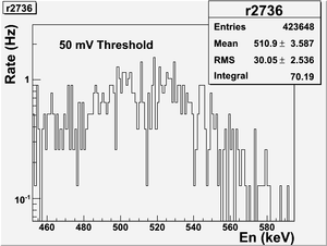
| 2736 | sample | on | In | det1 | 73 s | 50 | 2.4/960 | 3/1200 | 280/1120 | 250/1000 | FADC Chan#14 | Not connected | 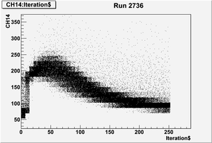 |
7.507 / 0.3 nA = 25.023 Hz/nA 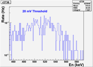
|
http://opweb.acc.jlab.org/CSUEApps/elog/entry/1666627
We took data for the annihilation counter detectors with their own configuratio
n and no fadc trheshold, but Threshold in the VME discriminator of 20mV.
The detector N.1 is plugged in:
fadc channel CH 14
TDC channel CH 9
/data/annihilation/
We have 2 differnt runs, one with the beam in the target of the annilitation cr oss insertet and one with no beam in the beam line.
Target out
Watch the ChroMox viewer as you move it out of position, so there is no longer a target in place.
Start a CODA run for 15 minutes
Data Analysis
Overlay of runs.
August Det #1 measurements with a source suggest a calibration of Aug 2011 Annihilation Counter Measurements.
510.998910 keV/39652.6 integrated channel
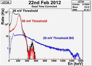
Just plot either run 2734 or 2735 and label with the threshold value of 20 mV
Replace run 2736 label with threshold 50 mV label
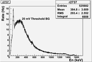
Replace run 2737 label with 20 mV Background label.
Replace titles with a Date of the experiment. Label axes "MeV and Hz"
set number size 0.4 and letter sizes 0.6
Dead time correction
- Find dead time.
Scaler:__________|-|__|-|__|-|__|-|__|-|___ 5 pulses
FADC scaler: ____________|-|_____________ 1 pulse
(5-1)/5=80% dead time.
- If I have 80% dead time, I should multiply my counts by 1/(1-80%)=5.
Erica's dead time calculation:
Dead time = L1A/L1
Erica Said
L1 or Level 1 is the incoming trigger. In this case is the detector signal (or the AND, when there is a coincidende, of the 2 detector signals) used as a start.
The L1A or Level 1 Accept is the signal coming from the VME CPU that tells to the rest of the electronics that it can read and accept trigger, because it is not busy processing the previous data.
My understand is: L1 is incoming triggers. L1A are those L1 that is accepeted (or executed).
So, L1A/L1 should be the live time.
mutiply the beam on data by a factor of 6 and leave the beam off data alone
