Difference between revisions of "Sadiq IPAC 2012"
| (29 intermediate revisions by 2 users not shown) | |||
| Line 1: | Line 1: | ||
| + | ='''Emittance Measurement of Varian Medical Linac'''= | ||
| + | |||
| + | Paper Submission Deadline Tues., May 15, 2012 | ||
| + | |||
| + | = Links = | ||
| + | |||
| + | Abstract submission: http://www.ipac12.org/abstractsubmission.htm | ||
| + | |||
| + | Ipac12 home: http://www.ipac12.org/index.htm | ||
| + | |||
| + | |||
= Abstract = | = Abstract = | ||
| − | Emittance of Varian High Rep-Rate Linac (HRRL) was measured with Optical Transition Radiation (OTR) at 14 MeV. Electron beam was observed at 10 <math>\mu m </math> thick Al screen. Quadrupole scanning method shows that | + | == Mine == |
| + | Emittance of Varian High Rep-Rate Linac (HRRL) was measured with Optical Transition Radiation (OTR) at 14 MeV. Electron beam was observed at 10 <math>\mu m </math> thick Al screen. Projection of beam appear to be sharper than Gaussian distribution, and super-Gaussian distribution were fitted. Quadrupole scanning method shows that horizontal and vertical are <math>11.4 \pm 0.6~\mu m</math> and <math> 9.3 \pm 1.8~\mu m</math> respectively. | ||
| + | |||
| + | |||
| + | Emittance of Varian High Rep-Rate Linac (HRRL) was measured with Optical Transition Radiation (OTR) at 14 MeV. Electron beam was observed at 10 <math>\mu m </math> thick Al screen. Projection of beam appear to be sharper than Gaussian distribution, and super-Gaussian distribution were fitted. Quadrupole scanning method shows that horizontal and vertical are 11.4 <math>\mu m</math> and 9.3 <math> \mu m</math> respectively. | ||
| + | |||
| + | |||
| + | Transverse Beam Emittance measurements of a 16 MeV Medical Linac | ||
| + | |||
| + | == Dr. Forest's == | ||
| + | |||
| + | Beam emittance measurements of a 16 MeV S-band High Repetition Rate Linac (HRRL) have been performed at Idaho State University's Idaho Accelerator Center (IAC). The HRRL is one of several low energy accelerators operating at the IAC. Originally, the linac | ||
| + | structure of the HRRL was similar to that used by a typical medical linac. The HRRL's RF system was upgraded to operate it at the maximum | ||
| + | repetition rate of 1 kHz. Currently, the HRRL beam line is being reconfigured into an achromat to be used as a positron source. The transverse beam emittance of the HRRL was measured to optimize the production of positrons using an intense electron beam on a Tungsten converter. In this paper we describe a beam imaging | ||
| + | system based on an OTR screen and a digital CCD camera, a MATLAB tool to extract beamsize and emittance, detailed | ||
| + | measurement procedures, and the results of measured transverse emittances for various beam currents and energies. | ||
| + | |||
| + | == Dr. Forest's and Dr. Freyberger's == | ||
| + | |||
| + | |||
| + | |||
| + | Beam emittance measurements of a 16 MeV S-band High Repetition Rate Linac (HRRL) have been performed at Idaho State University's Idaho Accelerator Center (IAC). The HRRL is one of several low energy accelerators operating at the IAC. Originally, the linac | ||
| + | structure of the HRRL was similar to that used by a typical medical linac. The HRRL's RF system was upgraded to operate it at the maximum | ||
| + | repetition rate of 1 kHz. The transverse beam emittance of the HRRL was measured to optimize the production of positrons using an intense electron beam on a Tungsten converter. In this paper we describe a beam imaging | ||
| + | system based on an OTR screen and a digital CCD camera, a MATLAB tool to extract beamsize and emittance, detailed | ||
| + | measurement procedures, and the results of measured transverse emittances for various beam currents and energies. Currently, the HRRL beam line is being reconfigured into an achromat to be used as a positron source. | ||
| + | |||
| + | = Introduction = | ||
| + | |||
| + | |||
| + | |||
| + | = Experiment Setup = | ||
| + | |||
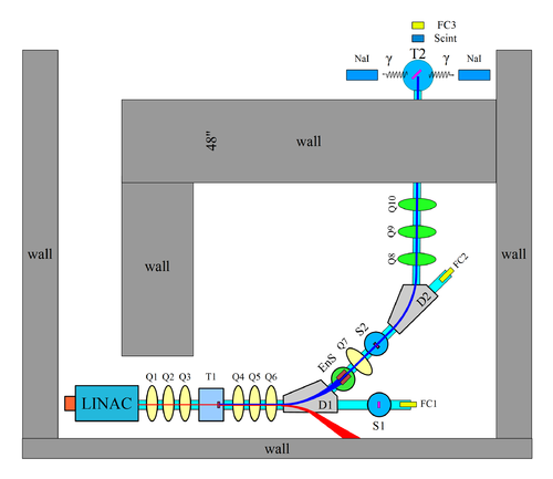
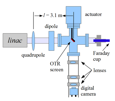
| + | Experimental setup is shown in the following two figures. | ||
| + | |||
| + | {| border="0" style="background:transparent;" align="center" | ||
| + | |- | ||
| + | | [[image:BeamLine_Yim_10-14-10.png | 500 px |thumb|Fig. HRRL beamline.]] || [[image:hrrl_2011_mar_emit_test_quad_scan_quad.png | 400 px |thumb|Fig. Imaging system for HRRL.]] | ||
| + | |} | ||
| + | |||
| + | We chose one of the quad at a time to do the scan and turned off all the other quads. Optical transition radiation was observed at OTR target. At the end of 0 degree beamline we have a Faraday cup to measure the charge of the beam. Camera cage system was located below the OTR target. There are 3 lenses used to focus lights from target to the CCD camera. Target can be pushed into or taken out of the beamline by the actuator at the top. | ||
| + | |||
| + | |||
| + | |||
| + | |||
| + | |||
| + | |||
| + | |||
| + | |||
| + | |||
| + | |||
| + | |||
| + | |||
| + | |||
| + | |||
| + | |||
| + | [https://wiki.iac.isu.edu/index.php/User:Setisadi Go back ] | ||
Latest revision as of 07:21, 11 April 2012
Emittance Measurement of Varian Medical Linac
Paper Submission Deadline Tues., May 15, 2012
Links
Abstract submission: http://www.ipac12.org/abstractsubmission.htm
Ipac12 home: http://www.ipac12.org/index.htm
Abstract
Mine
Emittance of Varian High Rep-Rate Linac (HRRL) was measured with Optical Transition Radiation (OTR) at 14 MeV. Electron beam was observed at 10 thick Al screen. Projection of beam appear to be sharper than Gaussian distribution, and super-Gaussian distribution were fitted. Quadrupole scanning method shows that horizontal and vertical are and respectively.
Emittance of Varian High Rep-Rate Linac (HRRL) was measured with Optical Transition Radiation (OTR) at 14 MeV. Electron beam was observed at 10 thick Al screen. Projection of beam appear to be sharper than Gaussian distribution, and super-Gaussian distribution were fitted. Quadrupole scanning method shows that horizontal and vertical are 11.4 and 9.3 respectively.
Transverse Beam Emittance measurements of a 16 MeV Medical Linac
Dr. Forest's
Beam emittance measurements of a 16 MeV S-band High Repetition Rate Linac (HRRL) have been performed at Idaho State University's Idaho Accelerator Center (IAC). The HRRL is one of several low energy accelerators operating at the IAC. Originally, the linac structure of the HRRL was similar to that used by a typical medical linac. The HRRL's RF system was upgraded to operate it at the maximum repetition rate of 1 kHz. Currently, the HRRL beam line is being reconfigured into an achromat to be used as a positron source. The transverse beam emittance of the HRRL was measured to optimize the production of positrons using an intense electron beam on a Tungsten converter. In this paper we describe a beam imaging system based on an OTR screen and a digital CCD camera, a MATLAB tool to extract beamsize and emittance, detailed measurement procedures, and the results of measured transverse emittances for various beam currents and energies.
Dr. Forest's and Dr. Freyberger's
Beam emittance measurements of a 16 MeV S-band High Repetition Rate Linac (HRRL) have been performed at Idaho State University's Idaho Accelerator Center (IAC). The HRRL is one of several low energy accelerators operating at the IAC. Originally, the linac structure of the HRRL was similar to that used by a typical medical linac. The HRRL's RF system was upgraded to operate it at the maximum repetition rate of 1 kHz. The transverse beam emittance of the HRRL was measured to optimize the production of positrons using an intense electron beam on a Tungsten converter. In this paper we describe a beam imaging system based on an OTR screen and a digital CCD camera, a MATLAB tool to extract beamsize and emittance, detailed measurement procedures, and the results of measured transverse emittances for various beam currents and energies. Currently, the HRRL beam line is being reconfigured into an achromat to be used as a positron source.
Introduction
Experiment Setup
Experimental setup is shown in the following two figures.
We chose one of the quad at a time to do the scan and turned off all the other quads. Optical transition radiation was observed at OTR target. At the end of 0 degree beamline we have a Faraday cup to measure the charge of the beam. Camera cage system was located below the OTR target. There are 3 lenses used to focus lights from target to the CCD camera. Target can be pushed into or taken out of the beamline by the actuator at the top.

