Difference between revisions of "TF EIMLab4 Writeup"
Jump to navigation
Jump to search
| (4 intermediate revisions by the same user not shown) | |||
| Line 2: | Line 2: | ||
= 1-50 kHz filter (20 pnts)= | = 1-50 kHz filter (20 pnts)= | ||
| + | |||
| + | |||
1.) Design a high-pass RC filter with a break point between 1-50 kHz. The break point is the frequency at which the filter's attenuation of the AC signal goes to 0(not passed). For a High pass filter, AC signals with a frequency below the 1-50 kHz range will be attenuated . | 1.) Design a high-pass RC filter with a break point between 1-50 kHz. The break point is the frequency at which the filter's attenuation of the AC signal goes to 0(not passed). For a High pass filter, AC signals with a frequency below the 1-50 kHz range will be attenuated . | ||
| Line 14: | Line 16: | ||
| Ohms || Farads || rad/s ||Hz | | Ohms || Farads || rad/s ||Hz | ||
|- | |- | ||
| − | | <math>10.5 </math>|| <math>1.25 \times 10^{-6}</math>|| 76190||12,126 | + | | <math>10.5 </math>|| <math>1.25 \times 10^{-6}</math>|| 76190||92 |
| + | |- | ||
| + | | <math>167600 \Omega </math>|| <math>10.3 \times 10^{-9}</math>|| 579||12,126 | ||
|} | |} | ||
Latest revision as of 19:04, 25 February 2011
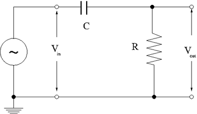
- RC High-pass filter
1-50 kHz filter (20 pnts)
1.) Design a high-pass RC filter with a break point between 1-50 kHz. The break point is the frequency at which the filter's attenuation of the AC signal goes to 0(not passed). For a High pass filter, AC signals with a frequency below the 1-50 kHz range will be attenuated .
| R | C | ||
| Ohms | Farads | rad/s | Hz |
| 76190 | 92 | ||
| 579 | 12,126 |
2.) Now construct the circuit using a non-polar capacitor.
3.)use a sinusoidal variable frequency oscillator to provide an input voltage to your filter.
4.)Measure the input and output voltages for at least 8 different frequencies which span the frequency range from 1 Hz to 1 MHz.
| Hz | Volts | Volts | |
5.)Graph the -vs-
phase shift (10 pnts)
- measure the phase shift between and
Questions
- compare the theoretical and experimentally measured break frequencies. (5 pnts)
- Calculate an expression for as a function of , , and .(5 pnts)
- Compare the theoretical and experimental value for the phase shift . (5 pnts)
- Sketch the phasor diagram for ,, , and . Put the current along the real voltage axis. (30 pnts)
- what is the phase shift for a DC input and a very-high frequency input?(5 pnts)
- calculate and expression for the phase shift as a function of , , and graph -vs . (20 pnts)
