Difference between revisions of "Kalyan 23 May 08 2.1"
| (2 intermediate revisions by the same user not shown) | |||
| Line 34: | Line 34: | ||
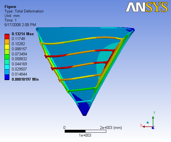
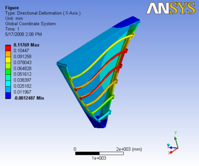
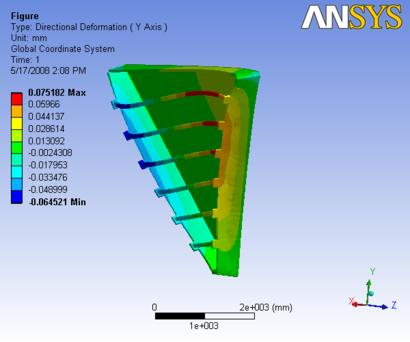
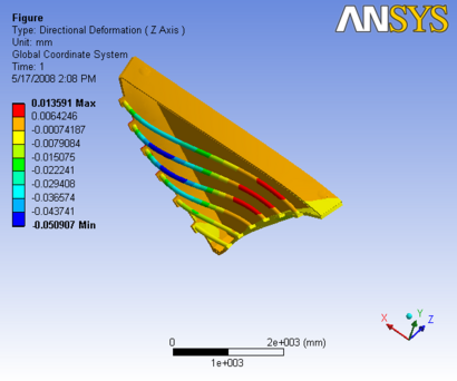
Figure 2: Images of Deflection for Sector 1 with 3.5 inch Diameter, 0.1 Inch thk carbon rods in D,X,Y,Z Directions respectively | Figure 2: Images of Deflection for Sector 1 with 3.5 inch Diameter, 0.1 Inch thk carbon rods in D,X,Y,Z Directions respectively | ||
| − | ==3.5 inch Dia, 0.2 Inch thk== | + | ==3.5 inch Dia, 0.2 Inch thk carbon rod== |
| Line 54: | Line 54: | ||
Figure 3: Images of Deflection for Sector 1 with 3.5 inch Diameter, 0.2 Inch thk carbon rods in D,X,Y,Z Directions respectively | Figure 3: Images of Deflection for Sector 1 with 3.5 inch Diameter, 0.2 Inch thk carbon rods in D,X,Y,Z Directions respectively | ||
| − | + | ==3.5 inch Dia, 0.3 Inch thk carbon rod== | |
| − | ==3.5 inch Dia, 0.3 Inch thk== | ||
| Line 74: | Line 73: | ||
Figure 4: Images of Deflection for Sector 1 with 3.5 inch Diameter, 0.3 Inch thk carbon rods in D,X,Y,Z Directions respectively | Figure 4: Images of Deflection for Sector 1 with 3.5 inch Diameter, 0.3 Inch thk carbon rods in D,X,Y,Z Directions respectively | ||
| + | |||
| + | |||
| + | |||
| + | [http://www.iac.isu.edu/mediawiki/index.php/Progress_reports Go back to PROGRESS REPORTS] | ||
| + | |||
| + | [http://www.iac.isu.edu/mediawiki/index.php/R3 Go back to R3] | ||
Latest revision as of 10:49, 20 May 2008
3 inch Dia, 0.1 inch thk carbon rod carbon rod
The report generated by ANSYS is available: File:Analysis O slice 3,0.1 1.pdf
|
 |
 |
|
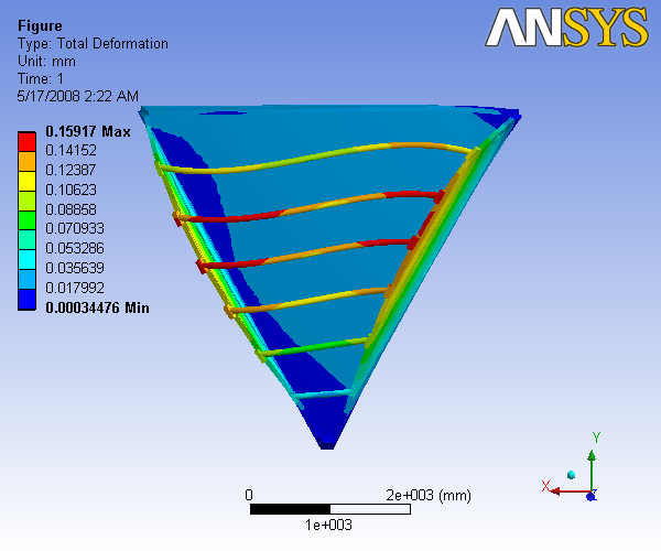
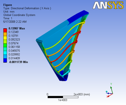
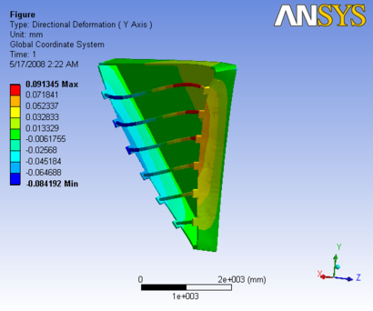
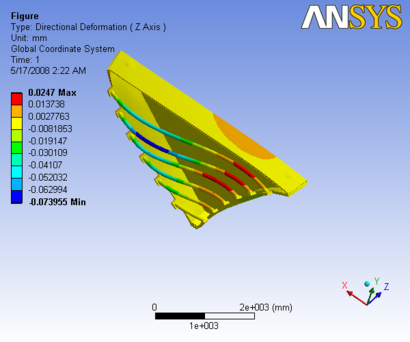
Figure 1: Images of Deflection for Sector 1 with 3 inch Diameter, 0.1 Inch thk carbon rods in D,X,Y,Z Directions respectively
3.5 inch Dia, 0.1 Inch thk carbon rod
The report generated by ANSYS is available: File:Analysis O 3.5,0.1 slice 1.pdf
|
 |
 |
|
Figure 2: Images of Deflection for Sector 1 with 3.5 inch Diameter, 0.1 Inch thk carbon rods in D,X,Y,Z Directions respectively
3.5 inch Dia, 0.2 Inch thk carbon rod
The report generated by ANSYS is available: File:Analysis O 3.5,0.2 slice 1.pdf
|
 |
 |
|
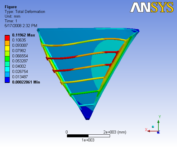
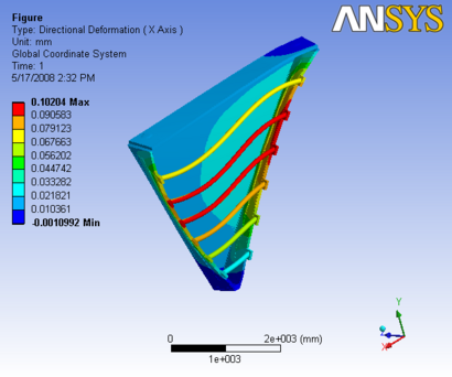
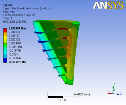
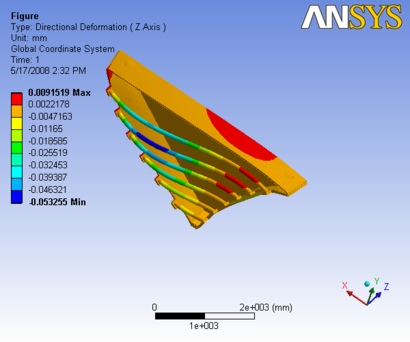
Figure 3: Images of Deflection for Sector 1 with 3.5 inch Diameter, 0.2 Inch thk carbon rods in D,X,Y,Z Directions respectively
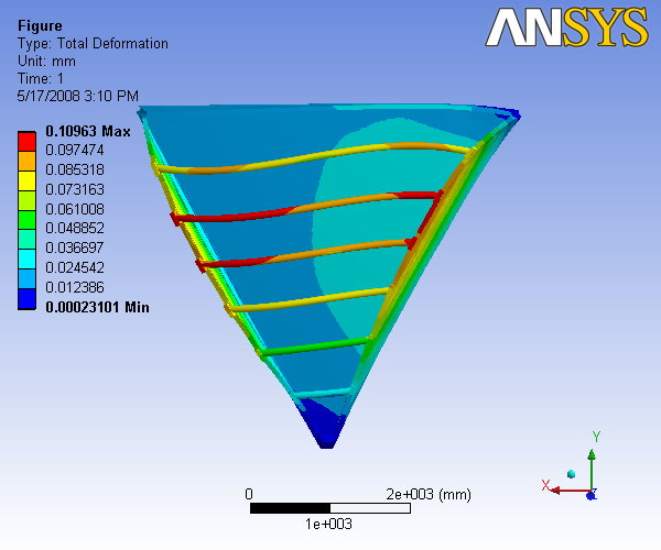
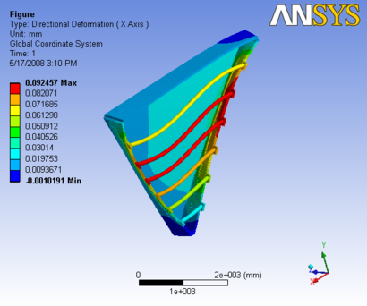
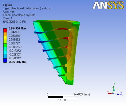
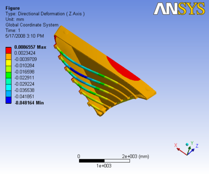
3.5 inch Dia, 0.3 Inch thk carbon rod
The report generated by ANSYS is available: File:Analysis O 3.5,0.3 slice 1.pdf
|
 |
 |
|
Figure 4: Images of Deflection for Sector 1 with 3.5 inch Diameter, 0.3 Inch thk carbon rods in D,X,Y,Z Directions respectively