Difference between revisions of "5-19-08"
Jump to navigation
Jump to search
| (55 intermediate revisions by the same user not shown) | |||
| Line 1: | Line 1: | ||
| + | [http://wiki.iac.isu.edu/index.php/Beam_Position_Monitor_Tests_in_HRRL Go Back] | ||
| + | |||
Tests of the beam position monitor and the FC using the HRRL | Tests of the beam position monitor and the FC using the HRRL | ||
= Position tests= | = Position tests= | ||
| Line 14: | Line 16: | ||
|scope picture | |scope picture | ||
|- | |- | ||
| − | | 80 || [[Image:BPM_position_80mA_1.png]] | + | | 80(early) || [[Image:BPM_position_80mA_1.png |200 px]][[Image:BPM_position_80mA_2.png |200 px]][[Image:BPM_position_80mA_3.png |200 px]] |
| − | | | ||
| − | | | ||
|- | |- | ||
| − | | | + | | 40 || [[Image:BPM_position_40mA_1.png |200 px]] [[Image:BPM_position_40mA_2.png |200 px]][[Image:BPM_position_40mA_3.png |200 px]] |
|- | |- | ||
| − | | 80 || | + | | 80(later) || [[Image:BPM_position_80mA(later)_1.png |200 px]] [[Image:BPM_position_80mA(later)_2.png |200 px]] [[Image:BPM_position_80mA(later)_3.png |200 px]] |
|- | |- | ||
|}<br> | |}<br> | ||
| Line 29: | Line 29: | ||
|- | |- | ||
|position change | |position change | ||
| + | | asym | ||
|scope picture | |scope picture | ||
|- | |- | ||
| − | | 5 turns clockwise of platform|| [[Image: | + | | 5 turns clockwise of platform|| 0.879 <math>\pm</math> 0.0623 || [[Image:5 turns clockwise_1.png |200 px]] [[Image:5 turns clockwise_1.png |200 px]] |
| + | |- | ||
| + | | 4 turn clockwise || 0.659 <math>\pm</math> 0.0149 || [[Image:1 turns counter clockwise_1.png |200 px]] | ||
|- | |- | ||
| − | | | + | | 3 turn clockwise || 0.646 <math>\pm</math> 0.169 || [[Image:1 turns (2nd) counter clockwise_1.png |200 px]] |
|- | |- | ||
| − | | || | + | | 2 turn clockwise || 0.8 <math>\pm</math> 0.080 || [[Image:1 turns (3rd) counter clockwise (80mAmp)_1.png |200 px]] |
|- | |- | ||
| − | | || | + | | 4 turns counter clockwise || 0.028 <math>\pm</math> 0.003 ||[[Image:12 turns counter clockwise_80mAmp.png |200 px]] |
| + | |- | ||
| + | | 0 turns from center || 0.135 <math>\pm</math> 0.159 ||[[Image:at center.png |200 px]] | ||
|- | |- | ||
| + | | 8 turns clockwise || 0.885 <math>\pm</math> 0.001 ||[[Image:8 turns clockwise.png |200 px]] | ||
| + | |- | ||
| + | | 6 turns clockwise || .778 <math>\pm</math> 0.002 ||[[Image:6 turns clockwise.png |200 px]] | ||
| + | |- | ||
| + | | 2 turns counter clockwise || 0.231 <math>\pm</math> 0.112 ||[[Image:2 turns counter clockwise.png |200 px]] | ||
| + | |||
|}<br> | |}<br> | ||
| Line 52: | Line 63: | ||
=FC performance= | =FC performance= | ||
| + | The JLab FC was placed (in AIR) 30 cm from the zero port window of the HRRL. A ground braid connected the BNC connector to the ground used by the accelerator RF. Without this ground there was even more RF pickup. The lower yellow trace represents the RF pulse from the HRRL which was running with 40 ns pulse widths at a rep rate of 205 Hz. | ||
{| border="1" cellpadding="20" cellspacing="0" | {| border="1" cellpadding="20" cellspacing="0" | ||
| Line 58: | Line 70: | ||
|scope picture | |scope picture | ||
|- | |- | ||
| − | | | + | | 2 || [[Image: FC_JLab_HRRL_2mA_40.jpg | 100 px]] |
|- | |- | ||
| − | | | + | | 5 || [[Image: FC_JLab_HRRL_5mA_96.jpg | 100 px]] |
|- | |- | ||
| − | | | + | | 20 || [[Image: FC_JLab_HRRL_20mA_160.jpg | 100 px]] |
|- | |- | ||
| − | | | + | | 40 || [[Image: FC_JLab_HRRL_40mA_190.jpg | 100 px]] |
|- | |- | ||
| − | | | + | | 80 || [[Image: FC_JLab_HRRL_80mA_230.jpg | 100 px]] |
|- | |- | ||
| − | | | + | |}<br> |
| + | [[Image:FC_JLAB_HRRL_Calib_5-19-08.jpg]] | ||
| + | |||
| + | |||
| + | |||
| + | |||
| + | [http://www.iac.isu.edu/mediawiki/index.php/HRRL Go back] | ||
| + | |||
| + | =Rise of table per rotation= | ||
| + | |||
| + | |||
| + | {| border="1" cellpadding="20" cellspacing="0" | ||
| + | |- | ||
| + | Measurement | ||
| + | |Turns | ||
| + | |h (cm) | ||
| + | |- | ||
| + | | Original position || 10.02 | ||
|- | |- | ||
| − | |} | + | | 10 turns ccw (down) || 9.03 |
| + | |- | ||
| + | | 10 turns ccw (down) || 7.00 | ||
| + | |- | ||
| + | | 10 turns cw (up) || 9.04 | ||
| + | |- | ||
| + | | 10 turns cw (up) || 10.04 | ||
| + | |- | ||
| + | | 10 turns ccw (down) || 9.05 | ||
| + | |- | ||
| + | | 10 turns ccw (down) || 7.00 | ||
| + | |- | ||
| + | | 10 turns ccw (down) || 4.94 | ||
| + | |- | ||
| + | |} | ||
| + | Where "h" is height of table, and "cw" and "ccw" stand for clockwise and counter clockwise respectively. | ||
| + | |||
| + | The average change of height by a turn is 0.19 cm, with standard deviation σ =0.1cm | ||
| + | |||
| + | [http://wiki.iac.isu.edu/index.php/Beam_Position_Monitor_Tests_in_HRRL Go Back] | ||
Latest revision as of 06:36, 5 February 2009
Tests of the beam position monitor and the FC using the HRRL
Position tests
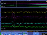
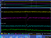
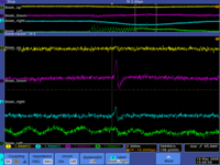
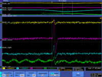
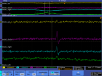
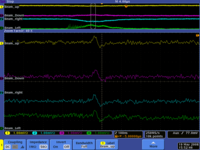
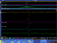
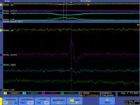
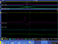
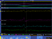
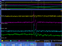
Below we see the first signals from the BPM
changed current
| Current | scope picture |
| 80(early) | 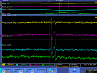 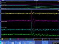 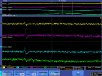
|
| 40 | 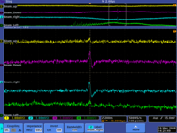 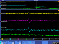 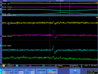
|
| 80(later) | 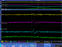 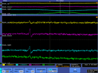 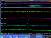
|
changed position
counter clockwise 1 turn
FC performance
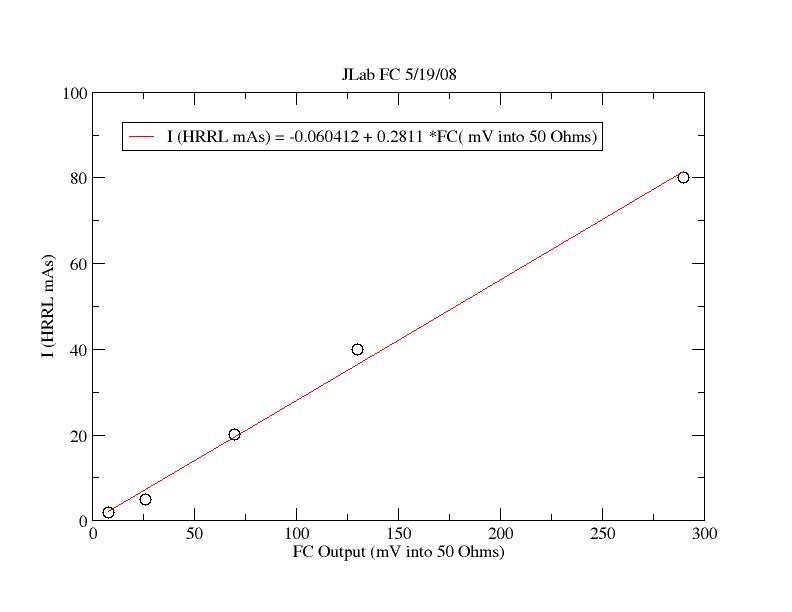
The JLab FC was placed (in AIR) 30 cm from the zero port window of the HRRL. A ground braid connected the BNC connector to the ground used by the accelerator RF. Without this ground there was even more RF pickup. The lower yellow trace represents the RF pulse from the HRRL which was running with 40 ns pulse widths at a rep rate of 205 Hz.
| Current (mA) | scope picture |
| 2 | 
|
| 5 | 
|
| 20 | 
|
| 40 | 
|
| 80 | 
|
Rise of table per rotation
Measurement| Turns | h (cm) |
| Original position | 10.02 |
| 10 turns ccw (down) | 9.03 |
| 10 turns ccw (down) | 7.00 |
| 10 turns cw (up) | 9.04 |
| 10 turns cw (up) | 10.04 |
| 10 turns ccw (down) | 9.05 |
| 10 turns ccw (down) | 7.00 |
| 10 turns ccw (down) | 4.94 |
Where "h" is height of table, and "cw" and "ccw" stand for clockwise and counter clockwise respectively.
The average change of height by a turn is 0.19 cm, with standard deviation σ =0.1cm
