Difference between revisions of "K 4-25-08"
| (One intermediate revision by the same user not shown) | |||
| Line 5: | Line 5: | ||
*Wire Loads are 1512N on all the 4 hole areas | *Wire Loads are 1512N on all the 4 hole areas | ||
| − | Case 1. No gravity | + | =Case 1. No gravity= |
{| align="center" border="0" | {| align="center" border="0" | ||
| Line 16: | Line 16: | ||
The remaining pictures with X, Y, Z Deformations are available at[[Remaining pictures of Case_1]] | The remaining pictures with X, Y, Z Deformations are available at[[Remaining pictures of Case_1]] | ||
| − | The analysis report is available at | + | The analysis report is available at [[Image:4_25_08_1.pdf]] |
| + | |||
| + | |||
| + | =Case 2. Ideal case of gravity= | ||
| + | |||
| + | {| align="center" border="0" | ||
| + | |- | ||
| + | |[[Image:4_25_08_2d.jpg| 600 px]] | ||
| + | |- | ||
| + | | Figure 4.25.08.2: Total Deformation in analysis Case 2 | ||
| + | |} | ||
| + | |||
| + | |||
| + | The remaining pictures with X, Y, Z Deformations are available at[[Remaining pictures of Case_2]] | ||
| + | The analysis report is available at [[Image:4_25_08_2.pdf]] | ||
| + | |||
| + | =Case 3. Chamber 3= | ||
| + | |||
| + | {| align="center" border="0" | ||
| + | |- | ||
| + | |[[Image:4_25_08_3d.jpg| 600 px]] | ||
| + | |- | ||
| + | | Figure 4.25.08.3: Total Deformation in analysis Case 3 | ||
| + | |} | ||
| + | |||
| + | |||
| + | The remaining pictures with X, Y, Z Deformations are available at[[Remaining pictures of Case_3]] | ||
| + | The analysis report is available at [[Image:4_25_08_3.pdf]] | ||
| + | |||
| + | =Case 4. Chamber 4= | ||
| + | |||
| + | {| align="center" border="0" | ||
| + | |- | ||
| + | |[[Image:4_25_08_4d.jpg| 600 px]] | ||
| + | |- | ||
| + | | Figure 4.25.08.4: Total Deformation in analysis Case 4 | ||
| + | |} | ||
| + | |||
| + | |||
| + | The remaining pictures with X, Y, Z Deformations are available at[[Remaining pictures of Case_4]] | ||
| + | The analysis report is available at [[Image:4_25_08_4.pdf]] | ||
| + | |||
| + | =Case 5. Chamber 5= | ||
| + | |||
| + | {| align="center" border="0" | ||
| + | |- | ||
| + | |[[Image:4_25_08_5d.jpg| 600 px]] | ||
| + | |- | ||
| + | | Figure 4.25.08.5: Total Deformation in analysis Case 5 | ||
| + | |} | ||
| + | |||
| + | |||
| + | The remaining pictures with X, Y, Z Deformations are available at[[Remaining pictures of Case_5]] | ||
| + | The analysis report is available at [[Image:4_25_08_5.pdf]] | ||
Latest revision as of 21:25, 25 April 2008
5 Analysis were carried out as follows.
All of them with Carbon rods, No Hexcel sheet, No mylar sheet. Left hinge was constrained, right hinge was allowed to move along the back Plate length(x-axis) and front face of the nose plate was constrained.
- Wire Loads are 1512N on all the 4 hole areas
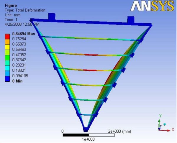
Case 1. No gravity
|
| Figure 4.25.08.1: Total Deformation in analysis Case 1 |
The remaining pictures with X, Y, Z Deformations are available atRemaining pictures of Case_1
The analysis report is available at File:4 25 08 1.pdf
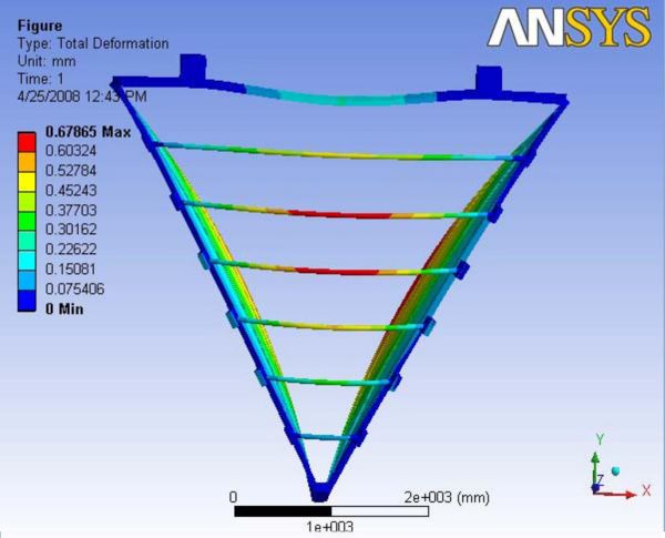
Case 2. Ideal case of gravity
|
| Figure 4.25.08.2: Total Deformation in analysis Case 2 |
The remaining pictures with X, Y, Z Deformations are available atRemaining pictures of Case_2
The analysis report is available at File:4 25 08 2.pdf
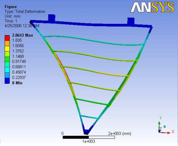
Case 3. Chamber 3
|
| Figure 4.25.08.3: Total Deformation in analysis Case 3 |
The remaining pictures with X, Y, Z Deformations are available atRemaining pictures of Case_3
The analysis report is available at File:4 25 08 3.pdf
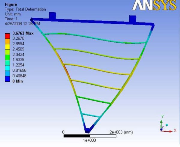
Case 4. Chamber 4
|
| Figure 4.25.08.4: Total Deformation in analysis Case 4 |
The remaining pictures with X, Y, Z Deformations are available atRemaining pictures of Case_4
The analysis report is available at File:4 25 08 4.pdf
Case 5. Chamber 5
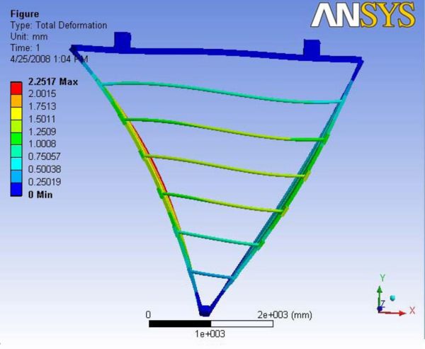
|
| Figure 4.25.08.5: Total Deformation in analysis Case 5 |
The remaining pictures with X, Y, Z Deformations are available atRemaining pictures of Case_5
The analysis report is available at File:4 25 08 5.pdf