Difference between revisions of "ReadoutBoardGerberFiles"
Jump to navigation
Jump to search
| (2 intermediate revisions by the same user not shown) | |||
| Line 1: | Line 1: | ||
| + | The Qweak readout board top layer has 4 connectors and the axial readout copper strips for measuring <math>\theta</math>. See the [http://www.jlab.org/~tforest/Qweak/ForwardTracker/StatusReports/images/FinalDesign/ReadoutBoard/GerberFiles/Qweak_ReadoutBoardTopLayer.gerber Top Layer Gerber File] for this layer, it should look like the picture below.<br> | ||
[[Image:ReadoutBoardBottomLayer.jpg]]<br> | [[Image:ReadoutBoardBottomLayer.jpg]]<br> | ||
| + | |||
| + | The Qweak readout board Bottom layer has 2 connectors and the Radial readout copper strips. See the [http://www.jlab.org/~tforest/Qweak/ForwardTracker/StatusReports/images/FinalDesign/ReadoutBoard/GerberFiles/Qweak_ReadoutBoardBottomLayer.gerber Bottom Layer Gerber File] for this layer, it should look like the picture below.<br> | ||
| + | |||
[[Image:ReadoutBoardTopLayer.jpg]]<br> | [[Image:ReadoutBoardTopLayer.jpg]]<br> | ||
Latest revision as of 17:53, 21 July 2007
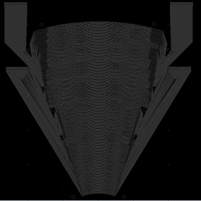
The Qweak readout board top layer has 4 connectors and the axial readout copper strips for measuring . See the Top Layer Gerber File for this layer, it should look like the picture below.

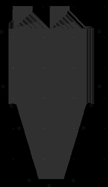
The Qweak readout board Bottom layer has 2 connectors and the Radial readout copper strips. See the Bottom Layer Gerber File for this layer, it should look like the picture below.
