Difference between revisions of "H Proposal Defense"
(→Topic) |
|||
| (884 intermediate revisions by 3 users not shown) | |||
| Line 1: | Line 1: | ||
| + | *Introduction | ||
| + | *Gas Electron Multiplication | ||
| + | *Detector Signal Size | ||
| + | *Summary | ||
| + | |||
=Topic= | =Topic= | ||
| − | The | + | The Performance of Thick Gaseous Electron Multiplier Preamplifiers (THGEM) as a Neutron Sensitive Detector. [[File: Proposal.pdf]] |
=Introduction= | =Introduction= | ||
| − | + | I propose to construct and measure the performance of a fission chamber instrumented with preamplifiers known as a Thick Gas Electron Multiplier (THGEM). This fission chamber is a chamber filled with an inert gas enclosing a fissionable target material, like Uranium or Thorium. A neutron of sufficient energy has the potential to interact with fissionable material producing heavy ions known as fission fragments. The fission fragments within 5 micron of the target's surface may escape the target as ions and ionize the gas in the chamber. Electrons freed from the ionization gas can enter the THGEM preamplifier producing secondary electrons which are directed to collectors using strong electric fields. | |
| + | |||
| + | |||
| + | A THGEM preamplifier is a perforated fiberglass board (PC board) clad with a conducting material. The design is based upon the Gas Electron Multiplier (GEM) invented by Fabio Sauli in 1997<ref name="Sauli1997">F. Sauli, et al, NIM A386, (1997) 531-534 </ref >. The GEM preamplifier is a 50 micron sheet of kapton that is coated on each side with 5 micron of copper. The copper clad kapton is perforated with 50-100 micron diameter holes separated by 100-200 micron in a staggered array . The THGEM preamplifier is a more macroscopic version of GEM that uses a 2 mm thick fiberglass sheet perforated with holes that are 2 mm in diameter. | ||
| + | |||
| + | |||
| + | Strong electric fields are established by supplying a potential difference between the two sides of the kapton, or the fiberglass for the case of the THGEM. The electric field lines transport liberated electrons through the preamplifier holes. For the GEM foils, the smaller diameter of the hole can provide sufficient amplification using a potential difference of 350 V between the two sides. On the other hand, the THGEM with the larger hole diameter requires a higher potential difference of about 2000 Volts to achieve similar amplifications. | ||
| + | |||
| + | |||
| + | The objective of this work will be to construct a THGEM based ionization chamber. The THGEM will follow a proven design <ref name="Agocs">G. Agocs, B. Clark, P. Martinego, R. Oliveira, V. Peskov,gand P. Picchi,JINST, 3, P020112, 2008 </ref > and use a resistive paste to reduce discharge events. The detector may be made sensitive to neutrons by doping the resistive paste with a fissionable material. The doping step will take place once a working THGEM equipped detector has been demonstrated. This fission chamber-like device will have the advantage of measuring the location of the incident neutrons that induced a fission event within the chamber by measuring the ionization signal using a segmented charge collector. | ||
| + | |||
| + | =Gas Electron Multiplication= | ||
| + | |||
| + | An electron from a primary ionization event needs to liberate more charge in order | ||
| + | to create a detectable signal. One method to accomplish this amplification uses strong | ||
| + | electric fields to accelerate the primary electron until it has sufficient energy to liberate | ||
| + | more electrons from the chamber gas. In a traditional drift chamber, an electric field is | ||
| + | established between two or more conducting wires. As an electron is accelerated towards a | ||
| + | wire, it may obtain sufficient energy to ionize the chamber gas producing secondary freed | ||
| + | electrons. The secondary electrons produced may themselves also be accelerated along the | ||
| + | electric field lines and cause further ionization in a process commonly referred to as an | ||
| + | avalanche. | ||
| + | |||
| − | + | [[Image: streamer.png | 250 px|thumb|Fig.A streamer (more than one avalanche) <ref name="Holtzhausen">JP Holtzhausen, Dr WL VoslooHigh "Voltage Engineering Practice and Theory" ISBN: 978 - 0 - 620 - 3767 - 7</ref> | |
| + | ]] | ||
| − | + | ===The Gas Electron Multiplier (GEM)=== | |
| − | |||
| − | = | + | The Gas Electron Multiplier (GEM), invented by Fabio Sauli <ref name="Sauli1997"/> in 1997, is a modern method using electric fields to create an avalanche condition. A GEM is a 50 micron thick kapton foil clad on both sides with 5 micron of copper. A staggered pattern of 50 micron diameter holes, equally spaced by distances comparable to the hole diameter, is etched into the copper clad foil. The small size facilitates the use of low voltages (300 Volts) to generate an electric field for amplification. By comparison, the typical drift chamber, operating on the same principle, would need more than 1 kV to establish a similar electric field. |
| − | |||
| − | The | + | Some noteworthy advantages and disadvantages of the GEM are given below. The GEM foil is flexible enough to be curved, allowing cylindrically shaped ionization chambers with larger active areas. Unfortunately, the micrometer scale of a GEM foil makes it susceptible to damage from sparking at high amplification voltages. When the voltage increases from 525V to 600V (regardless of the card's pattern or the hole's geometry), the operating voltage range decreases to about 450 V or less as shown in Figure 3 <ref name="A.Bressan1999">A.Bressan, et al, NIM A 424 (1999) 321—342</ref >. GEM has a low noise signal because of the relatively low operating voltage, also the micrometer scale hole diameter increases the electric field flux through the holes, so a relatively high gain is obtained in the range of the operating voltage. |
| − | |||
| − | |||
| − | [[Image:Generic_SideView_GEMDetector.jpg]] | + | {| border="1" cellpadding="4" |
| + | |- | ||
| + | |[[Image:Generic_SideView_GEMDetector.jpg |thumb| Fig.1 Gas electron multiplication by three preamplifiers]] ||[[file:hole_electric_filed.png | thumb|Fig.2 Electric filed distribution in the holes]] || [[file:GEM_gain_spark.png| thumb| Fig.3 Gain and sparking as function of Voltage<ref name="A.Bressan1999"/>]] | ||
| + | |} | ||
| − | The | + | ===The Thick Gas Electron Multiplier (THGEM)=== |
| − | + | A Thick Gas Electron Multiplier (THGEM) is basically a GEM foil which has been scaled from micrometer to millimeter. A THGEM card is made from FR4/G10 clad on both sides with copper. The THGEM cards for this work are 12X12 cm square plates that are 1 mm thick and coated with 17 um thick copper cladding.2 Each card is chemically etched to leave a copper frame that surrounds an area of 100 cm2 as shown in Figure 4.A thin layer (around 5 micron) of ED-7100 resistive paste is applied (Figure 5) to allow potential �difference between the top and bottom layers and provide some spark protection by limiting the current flow along the surface. The card is machined to have 0.5mm diameter holes. The resistive paste near the holes is machined away to form a 0.2 mm thick rim around the hole. The holes are formed in a staggered array with a pitch of 0.8 mm. | |
| − | + | The THGEM cards are fixed in place to have the holes of each THGEM card aligned | |
| + | by the holders and separators in each corner. The cards are separated from each other by | ||
| + | a vertical distance of approximately 2.6 mm. A drift voltage card, or cathode, made of | ||
| + | copper paper is placed at the top of the cards at a distance of 2.6 - 4 mm from the closest THGEM card. The THGEM cards are placed inside a chamber made of two sheets of machined ertalyte (plastic), with a kapton window on the upper piece as shown in Figure 6. | ||
| − | |||
| − | The | + | The gas chamber is constructed using two 29.5X29.5X1.25 cm sheet of ertalyte plastic sheets that are bolted together by a number of M3 plastic screws located around the detector window to form a well closed cavity around the THGEM cards away from the surrounding atmosphere. The ionization gas, 90/10 percent Ar/CO2 mixture, flows in the cavity with a pressure of 1 atm. |
| − | |||
| − | |||
| − | |||
| − | |||
| − | |||
| − | + | {| border="1" cellpadding="4" | |
| + | |- | ||
| + | | [[File: THGEM_2.jpg |250 px|thumb|Fig.5 10.0X10.0 cm copper frame after etching]] || [[ File: THGEM_3.jpg|250 px |thumb|Fig.6 Thin layer of Ed7100 paste on the FR4 card]] | ||
| + | |} | ||
| − | + | [[File: THGEM_front.jpg | 250px|thumb| Fig.7 THGEM's chamber]] | |
| − | + | ||
| + | A read out plane exists on the bottom the detector. It consists of �different width cop- | ||
| + | per strips that are organized to have the same pitch such that the upper strip width is 50 | ||
| + | micron and lower strip is 150 micron; the two strips are separated by a 25 or 50 micron | ||
| + | thick layer of kapton. Both of the strips are glued on a 100 micron FR4 plate to achieve | ||
| + | reasonable | ||
| + | flatness as shown in Figure 8. The read out plane is vertically separated by a | ||
| + | distance of 0.5 mm from the closest THGEM card and it is connected to 16 connectors, | ||
| + | each connector has 20 traces. The 16 connectors are sent to a 130 pin adapter allowing the | ||
| + | use of a digitization card known as the VFAT card which sends a digital signal to a break | ||
| + | board and then to the DAQ system. | ||
| + | |||
| + | |||
| − | |||
| − | + | [[File: read_out_plate_design.png | 250px|thumb| Fig.8 Read out plate design. ]] | |
| − | + | THGEM preamplipfier is robust with a higher operating voltage and relatively higher gain with the least discharge. It has 0.2mm rim, 1 mm thick insulator and 2.6mm vertically separating distance from the next THGEM card, so the probability of discharge is minimized either in the card itself or with the other THGEM cards. But the detector may have a higher noise compared to that of the GEM preamplifier. | |
| + | =Detector Signal= | ||
| − | + | ===Ionization=== | |
| + | Ionization is the liberation of an electron from the confines of an atom. The minimum amount of energy required to liberate the electron is referred to as the ionization energy. Energy transferred to the electron in excess of this ionization energy will appear in the form of the ejected electron's kinetic energy. Photons or charged particles like fission fragments interacting with a gas volume can induce ionization. The ionization process depends stochastically on the ionization cross section which is mainly affected by the fission fragment energy, type of the fission fragment (heavy or light), the gas pressure in the chamber, and the atomic properties of the gas. Generally, the amount of energy needed to have an ionization event in a gas is the same on average <ref name="William"/>, regardless of the incident particle type or energy as shown in the following table for argon gas. | ||
{| border="1" cellpadding="4" | {| border="1" cellpadding="4" | ||
|- | |- | ||
| − | |Type || | + | |Type of particle and its energy || 9 keV x-rays || 10 keV electrons || 40 keV electrons || x-rays Ar-37(K-capture)(5-25 keV) + beta ||alpha 7.68 MeV || 340 MeV protons |
|- | |- | ||
| − | | | + | |Energy per ion-electron pair (eV) || 27.9 <math>\pm</math> 1.5 || 27.3 || 25.4 || 27.0 <math>\pm</math>0.5 || 26.25 || 25.5 |
| + | |} | ||
| + | |||
| + | ===Gas Ionization by Fission Fragments=== | ||
| + | |||
| + | Fission fragments are also a source of ionization when they penetrate an Argon gas chamber. The energy used for such an event is highly dependent on the fission fragment mass and velocity. At low fragment velocities, recoiling becomes a competitive process that decreases the probability of ionization. In the case of a high velocity fragment, the probability of ionizing the gas increases to be closer to that of the alpha particles as they are penetrating the same medium. | ||
| + | |||
| + | The ionized nuclei that are ejected from a heavy nucleus that has undergone the fission process can ionize atoms in the vicinity of the fission event. The fission fragments have path lengths in matter which are on the order of microns. The energy loss process that these fission fragments undergo over the short range may be astochastically described in terms of three steps; as the fission fragment is totally ionized, fission fragment is exchanging the charge with the gas atoms, and as the fission fragment is totally neutralized. | ||
| + | |||
| + | First, the total energy of a fission fragment without a bound electron is given by: | ||
| + | |||
| + | <math> E = \frac{k Z_1 Z_2 e^2}{r} + \frac{1}{2} M v^2 </math> | ||
| + | |||
| + | where '''<math>Z_1,M</math>''' and '''v''' are the atomic number, the mass, and the velocity of the fission fragment directly after the fission reaction. The coulomb force represents the repulsion force between the ionized gas atoms and fission fragments, as well as the attraction force between the fission fragment and electrons. The second term dominates until the fission fragment begins to probe the charge within the neutral ionization gas atoms. | ||
| + | |||
| + | When the fission fragment decelerates, a charge exchange starts between the fission fragment and gas atoms, as the electrons are either scattering away from the fission fragment nucleus or attached to it as it is in motion. The total energy loss of the fission fragment suggested by Bohr in 1940 is given as :<ref name="Hyde">Earl K. Hyde,The Nuclear Properties of the Heavy Elements 3,Denver Publications, 1971, p 195-210 </ref> | ||
| + | |||
| + | |||
| + | <math> \frac{1}{N} \frac{dE}{dx} = \frac {4 \pi e^4}{mv^2} (Z_1^{eff})^2 Z_2 \log\frac{1.123mv^3}{w e^2 Z_1^{eff}} + \frac {4 \pi e^4}{M_2 v^2} Z_1^2 Z_2^2 \times \log\left(\frac{M_1 M_2}{M_1 +M_2} \frac {v^2 a_{12}^{scr}}{Z_1 Z_2 e^2}\right) </math> | ||
| + | |||
| + | where '''N''' is the number of particles of the stopping medium per cubic centimeter, '''<math>M_1</math> ''' and '''<math>M_2</math>''' are masses of the fragment and the absorber,'''<math>Z_1</math> ''' and '''<math>Z_2</math>''' are the atomic number of the fragment and the absorber, '''e''' is the electron charge, '''v''' is the fragment velocity, '''<math>Z_1^{eff}</math> ''' is the charge of the fragment, changes from 20 for the beginning of the | ||
| + | track to a value of 2 close to the end of the track. '''<math>a_{12}^{scr} </math>''' is an impact parameter which tells at what distance the energy loss in the nuclear collisions is effectively zero owing to the screening of the charges of the nuclei by the atomic electrons, '''<math> w = I/\hbar </math>''' is the average oscillation frequency of the electrons in the atom. | ||
| + | |||
| + | |||
| + | This formula is an initial estimation of the total energy loss by the fission fragment under each stage of charge carrier exchange between the fission fragment and the gas atoms. It relies on how well Z-effective is estimated at each ionization step. | ||
| + | Consequently, the first term is dominant in the beginning of the interaction between the fission fragment and the ionization gas. The second term dominates close to the end of the fission fragment track.<ref name="Hyde"/> | ||
| + | |||
| + | Bethe's theory is commonly used to estimate the energy loss for fission fragments. It involves using a diverse model for the effective charge obtained based on energy loss data.<ref name="Rykov">V.A Rykov, atomic energy,vol83,No.1,1997 </ref> | ||
| + | |||
| + | <math> -\frac{dE}{dx} [\frac{MeV}{mg/cm^3}]= 3.072\times 10^{-4}\left(\frac {Z^{eff}}{\nu/c}\right)^2 \left(\frac {Z_m}{A_m}\right) ln\left(\frac {m_e \nu^2}{I}\right)</math> | ||
| + | |||
| + | |||
| + | <math> Z_{eff}=Z \left[1-A e^{-B\frac{\nu}{\nu_o Z^{\frac{3}{2}}}}\right] </math> | ||
| + | |||
| + | where '''Z''' is the nuclear charge of the fission fragment, <math>'''\nu_o'''</math> is the speed of the electron in first Bohr orbit, <math>'''\nu'''</math> is the speed of the ion, '''<math>Z_m , A_m </math>''' are the nuclear charge and the atomic mass of the medium, <math>'''m_e''' </math> is the mass of the electron, '''<math>I= KZ_m </math>''' is the mean excitation energy of the atomic electrons of the medium of atomic number '''<math>Z_m</math>'''. '''A''','''B''' are the fitting parameters dependent on the medium, for example A=0.92, B= 0.72 for Light fission fragments. A=0.99, B= 0.82 for heavy fission fragments are they are passing Ar/CH4 (95/5 percent) medium.<ref name="Biwas">D. C. Biswasa, M. N. Raob and R. K. Choudhury,NIM,Volume 53, Issue 3, 1 March 1991, Pages 251-254 </ref> | ||
| + | |||
| + | The final step describes the neutrally charged fission fragment. The probability of ionization is very low during this step because of the fission fragment's neutral charge and low kinetic energy. | ||
| + | The lowest energy at which a fission fragment can ionize a gas is expected to be equivalent to the energy of its weakest bound state electron which can be between 15.7 eV and 3.2 keV. | ||
| + | In more specific studies that are based on classifying the fission fragments into light and heavy fission fragments, the researchers tried to measure the amount of fission fragment energy consumed by processes other than ionization. The energy is referred to as the ionization defect energy<math>\Delta E </math>:<ref name="Valentine"/> | ||
| + | |||
| + | <math> \Delta E = E - I w_{\alpha} </math> | ||
| + | |||
| + | where '''E''' is the energy of the primary particle, '''I''' is the number of ionization events, and '''<math> w_{\alpha} </math>''' is the amount of energy use to produce an ion pair. Light fission fragments have a measured <math>\Delta E </math> of 2.5 MeV when their initial energy was energy 67 MeV. <ref name="Valentine">J.M. valentine, C.Curran, Reports on progress in physics,21, 1 (1958) 1-29 </ref > and heavy fission fragments have measured <math>\Delta E </math> of 4.2 MeV when their initial energy on average was 98 MeV. <ref name="Valentine">J.M. valentine, C.Curran, Reports on progress in physics,21, 1 (1958) 1-29 </ref > | ||
| + | |||
| + | The ionization defect energy experimentally indicates that you need lowest kinetic energy a fission fragment need to ionize the gas is actually higher than the fragments least bound electron binding energy. | ||
| + | |||
| + | ===The Neutron fission Cross Section for U-238 and Th-232=== | ||
| + | |||
| + | The cross section is defined by the following equation :<ref name="Ahmed"/> | ||
| + | |||
| + | <math> \sigma(E) = \int \frac{d\sigma}{d\Omega} . d\Omega </math> | ||
| + | |||
| + | where | ||
| + | |||
| + | <math> \frac{d\sigma}{d\Omega} = \frac{1}{\Phi}\frac{dN}{d\Omega} </math> | ||
| + | |||
| + | Where '''<math> \Phi </math>''' is the number incident particle per uni area per unit time, '''dN''' is the average number of particles per unit time that interacted per unit solid angle, and '''<math>\Omega</math>''' is the solid angle. | ||
| + | Since the cross section has an area unit (barn), some authors define this quantity as the area to which the particle is exposed to make an interaction. <ref name="Ahmed">Syed Ahmed, Physics and Engineering of Radiation Detection (Academic Press 2007) </ref> The cross section values are represented as a function of energy that gives the value of the cross section for each energy value and shows the resonance peaks. A theoretical description of the neutron fission cross section curve is not available, but statistically it is possible to evaluate the parameters for an assumption that describes part of the cross section curve within a certain error.<ref name="Hyde"/> | ||
| + | |||
| + | Neutron fission is one of the interactions that commonly takes place spontaneously or under certain experimental conditions. An incident neutron depositing sufficient energy in a nucleus to enable the nucleus to overcome the Coulomb barrier will cause the nucleus to split into fragment ligher nuclei (fragments) and particles. The new products interact with the surrounding medium depending on their energy and the type of the medium that contains them. | ||
| + | |||
| + | Both U-238 and Th-232 are members of the actinides group. They are characterized by relatively high neutron fission cross sections for fast neutrons with fission thresholds above the thermal neutron energy. The fission reaction in both elements is expected to eject 1-2 neutrons when the incident neutron energy is between 5-10 MeV as shown in Fig.9 and Fig.10. | ||
| + | |||
| + | |||
| + | {| border="1" cellpadding="4" | ||
|- | |- | ||
| − | | | + | |[[ File:ENDF_GEAN4_U238_fxsection.png |250 px]] ||[[File: Th_232_reference.png|250 px]] |
|- | |- | ||
| − | | | + | |Fig.9 U 238 fission cross section || Fig.10 Th 232 fission cross section <ref name="endf_Th_232_JEFF1.3">http://www.nndc.bnl.gov/exfor/servlet/E4sMakeE4 </ref> |
| + | |} | ||
| + | |||
| + | ===The Signal Size=== | ||
| + | |||
| + | |||
| + | An electron, freed by ionization and immersed in an external electric field, can ionize other atoms in a gas volume as a result of its acceleration in the external electric field. The number of additional freed electrons can be determined in terms of the external electric field (E), the pressure of the surrounding gas (P), and two fit parameters (A & B) which depend on the gas properties as shown in the equation <ref name="William"/> | ||
| + | |||
| + | <math> \frac {\alpha}{P}= Ae^{(\frac{-BP}{E})} </math> | ||
| + | |||
| + | The parameter <math>\alpha</math> is known as the Townsend coefficient. In the case of a THGEM preamplifier, an electric field (E) of <math>2 \times 10^4 \frac{\mbox{V}}{\mbox{cm}}</math> is established when a potential difference of 2 kV is applied between the top and bottom sides of the plate that are 0.1 cm apart. In this work, the gas chamber contains a 1 Atm mixture that is 90% Argon and 10 % C02 by volume. The parameters from reference <ref name="Sharma"> A.Sharma,F. Sauli, first tawsend coefficients measurements for argon gas european organization for nuclear research (1993) </ref > are not given for this mixture. To estimate the THGEM pre-amplification, the A and B parameters for a 96/4 percent mixture gas mixture were used which are 5.04 <math>\frac{1}{\mbox{cm Torr}}</math> and 90.82 <math>\frac{\mbox{V}}{\mbox{cm Torr}}</math> respectively . | ||
| + | |||
| + | Using the above equation we would expect <math> (\alpha)</math> to be about <math>121</math> per cm (which is a factor of 30 less than the coefficient for a GEM foil). A free electron traveling through the 0.1 cm THGEM hole should produce 12 additional freed electrons due to the Electric field of the THGEM pre-amplifier. We would expect a single freed electron to produce a maximum of <math>10^3</math> electrons if it traverses three THGEM pre-amplifiers. | ||
| + | |||
| + | |||
| + | The number electrons emitted from a fission fragment is <math>5.1X10^4/cm^3.s </math> as result of a 30 MeV proton projected toward a U-238 target,<ref name=""> M. Facina "A gas catcher for the selective production of radioactive beams through laser ionization" mater thesis, Leuven 2004 </ref > while GEANT4 simulation of Cd-123 ionization gets the same result when it is traveling in 50 atm Ar/CO2 gas.(Cd-123 with 81.6 MeV is one of the fission fragment of a fission event for a 1 MeV neutron projected toward U-238). So the expected signal for the fission fragment detected by 50 ohm oscilloscope is roughly 2-20 mV at 50 ns.For a single ionization event, the THGEM detector signal would be small, while for a fission event the number of freed electrons will be substantially larger resulting in a large signal. | ||
| + | |||
| + | ===The Efficiency of THGEM=== | ||
| + | |||
| + | [[File:Efficiency_U238.png|250 px |thumb| Fig.11 The probability a fission event in U 238]] | ||
| + | |||
| + | |||
| + | The efficiency of a detector is the ratio of the detected events to the total number of events entering the detector. | ||
| + | In order to detect a neutron entering the gas chamber the neutron must induce fission and the resulting fragments must ionize the gas. The cross-section for U-238(n,f) is given above in Fig.9. The probability of a fission event for a <math>1 cm^3</math> U-238 target varies from 1 to 5 % as shown in Fig.11. | ||
| + | The probability of a fission fragment escaping into the ionization gas is also required to calculate the detector's efficiency. | ||
| + | The number of fission fragments that escape from the surface of a UO3 film relative to the number of fission events is given by the following formula<ref name="Hudler">J.C.Hudler rdiation measurements 43,S334-S336, 2008 </ref>: | ||
| + | |||
| + | |||
| + | <math> \frac{N}{A} = \frac {\ln(\frac{d}{R_T}+ 0.5)}{8\pi[1-\frac{d}{R_T}] + \frac{d}{R_T}} </math> | ||
| + | |||
| + | where <math>N</math> is the number of fission fragments that escaped from the surface per unit area, A represents the number of fission interactions per unit volume, d is The thickness of film (um) and <math>R_T</math> is The mean range of the fission fragments (12.07 um). | ||
| + | |||
| + | Assuming that the number of fission fragments is : | ||
| + | |||
| + | |||
| + | <math> N = \int_{V_1} A \frac{cos\theta}{4\pi r^2} dV + \int_{V_2} A \frac{cos\theta}{4\pi r^2} dV </math> | ||
| + | |||
| + | and the average range of the fission fragment through the emulsion <math>R_E</math> is : | ||
| + | |||
| + | <math> <R_E> =<R_T> - <r> </math> | ||
| + | |||
| + | where <r> is the fission fragment's range in the thin film. | ||
| + | |||
| + | |||
| + | |||
| + | {| border="1" cellpadding="4" | ||
|- | |- | ||
| − | | | + | |[[File:ff_U238.png|250 px|thumb|Fig.12 The probability of a fission fragment escaping into the ionization gas]] |
| + | |} | ||
| + | |||
| + | =Summary= | ||
| + | |||
| + | |||
| + | Thick gas electron multipliers (THGEM) will be used to pre-amplify a fission chamber used to detect the location of fast neutrons within the detector. The detector will be built using a U-238 or Th-232 fission target, depending on availability, to take advantage of the large neutron fission cross section between 0.1 - 1 barn. A fission event, in the above targets, stochastically ejects a fission fragment having an energy of 65 to 100 MeV that may lose energy in the form of ionization in a Ar/CO2 gaseous medium surrounding the fission interaction and free on average <math> 10^4 </math> electrons. The electrons are directed by a drift electric field towards a THGEM preamplifier and, using three TGEMS, are amplified 10^6 to 10^7 times. The electrons are collected by a wire mesh read out producing a signal between 2 - 20 mV. | ||
| + | |||
| + | =For Later= | ||
| + | |||
| + | |||
| + | == Manufacturing Environment and Detector Aging== | ||
| + | |||
| + | Gaseous Detector manufacturing environment is always established to avoid any external effect that may interrupt the detector work. These effects come from the surrounding atmospheric environment of the detector like oxidization and dust accumulation. Also the effects appear in the working environment for the detector as it is surrounded with a noble gas like argon with contaminants under a high electric field effect; this produces chemical radicals attracted to the anode and causes non conducting anode. Finally, coating the THGEM cards by deposition used under a high electric field produces secondary electron emission from the coating, as a result reducing the life time of the of the THGEM cards.<ref name="Grupen">Particle Detectors, Claus Grupen & Boris Shwartz, 2nd edition, 2008 </ref> | ||
| + | |||
| + | Decrease the effect of the detector aging can relatively be controlled. Working in a clean room helps to avoid the contaminants carried by the surrounding atmosphere, and adding filters to the gas source decreases the contaminants carried by the gas. | ||
| + | |||
| + | |||
| + | {| border="1" cellpadding="4" | ||
|- | |- | ||
| − | | | + | |[[File:THGEM_signal.png|250 px|thumb|Fig. Double THGEM signal with electronic noise<ref name="Chenchik2004"/> ]] || [[ File:THGEM_double_signal.png |250 px|thumb|Fig. Double Fig.Signal produced when the gain is 220 and 180 respectively<ref name="Bondar"/>]] |
|} | |} | ||
| − | |||
| − | |||
| + | [[Least fission fragment K.E needed for ionization]] | ||
| + | |||
| + | [[Ionization and Number of the the electrons produced]] | ||
| + | |||
| + | The sensitivity of THGEM as a neutron detector mainly depends on neutron energy range, material cross sections for ionization, neutrons rates of interactions, detector mass, background, noise (sparking and electronic devices used to collect the signal), materials surrounding the detectors and the strength of the electric field.<ref name="James"/> <ref name="William">William R. Leo,Techniques for nuclear and particle physics experiments,1st edition,Springer Verlag, 1995.</ref> | ||
| + | |||
| + | ===Radiation Backgound for Th-232 and U-238 Decay=== | ||
| + | |||
| + | The background energy spectrum for Th-232 has a main peak for alpha decay of energy 4082.8(14) keV combined with gamma rays of energy 63.81(1) keV and intensity 26.3(13) percent.<ref name="Th-232"> http://home.fnal.gov/~hannahnp/decay/decay.html, Jan.5 2011,http://atom.kaeri.re.kr/cgi-bin/nuclide?nuc=Th-232</ref >. | ||
| + | |||
| + | |||
| + | U-238 has also a close background spectrum as being mainly an alpha emitter, but decay alpha energy is 4274(5) keV with less gamma | ||
| + | intensity 1.02(15) percent when its energy is 113.5(1) keV.<ref name="U-238"> Fermilab,http://home.fnal.gov/~hannahnp/decay/decay.html, Jan.5 2011,http://home.fnal.gov/~hannahnp/decay/U238.html</ref > | ||
| − | |||
{| border="1" cellpadding="4" | {| border="1" cellpadding="4" | ||
|- | |- | ||
| − | |[[ File: | + | |[[File:Th-232_decay_info.png|250 px|thumb| .<ref name="Th-232_d"> http://home.fnal.gov/~hannahnp/decay/decay.html, Jan.6 2011,http://atom.kaeri.re.kr/cgi-bin/decay?Th-232%20A </ref >]] || [[File:U-238_decay_info.png|250 px|thumb| .<ref name="U-238_d"> http://home.fnal.gov/~hannahnp/decay/decay.html, Jan.6 2011,http:http://atom.kaeri.re.kr/cgi-bin/decay?U-238%20A </ref >]] |
|} | |} | ||
| − | + | The ionization from alpha particles and gamma rays is considered negligible compared to the one for any fission fragment,because of the enormous difference in mass, charge and kinetic energy. But when the fission fragments are absent, there will always be a signal representing the alpha decay. | |
| − | + | ||
| − | + | ||
| + | [[File:hadler_on_energy_absorption_effects_in_U_Th_thinfilms.pdf]] | ||
| + | |||
| + | |||
| + | Sensitivity of the THGEM as neutron detector for gamma radiation is minimized by properties mentioned previously about THGEM low amplification factor, also U-238 as a high cross section for gamma absorption in the desired energy range. | ||
| − | |||
| − | |||
| − | + | [[file:GEM_canonical.png | thumb| Fig.5 Gain for canonical GEM<ref name="A.Bressan1999"/>]] | |
| − | + | [[File: THGEM_without_paste.jpg | 250px|thumb| Fig.7 THGEM preamplifier before applying the paste]] | |
| + | [[file:GEM_cat.png | thumb|Fig.6 Gain for CAT GEM<ref name="A.Bressan1999"/>]] | ||
| + | [[file:GEM_types.png | thumb|Fig.3 Different types of GEM <ref name="A.Bressan1999"/>]]|| | ||
| − | |||
| − | + | Neutrons are classified depending on their kinetic energy into three types: thermal, intermediate, and fast neutrons. The following table shows each type of neutrons and the energy range that they belong to. | |
| − | |||
| − | 7-Ch. Jammes, P. Filliatre, B. Geslot, L. Oriol, F. Berhouet, J-F. Villard, | + | {| border="1" cellpadding="4" |
| + | |- | ||
| + | |Type || Energy | ||
| + | |- | ||
| + | |Thermal || 0.025 eV | ||
| + | |- | ||
| + | | Intermediate || 1 keV – 500 keV | ||
| + | |- | ||
| + | | Fast || > 0.5 MeV | ||
| + | |} | ||
| + | <ref name="Dostal">General principles of neutron activation analysis, J. Dostal and C. Elson,p 28 Figure 2.3.</ref> <ref name="James">7-Ch. Jammes, P. Filliatre, B. Geslot, L. Oriol, F. Berhouet, J-F. Villard, | ||
“Research activities in fission chamber modeling in support of the nuclear energy industry”, ANIMMA International Conference, 7-10 | “Research activities in fission chamber modeling in support of the nuclear energy industry”, ANIMMA International Conference, 7-10 | ||
| − | June 2009, Marseille, France. | + | June 2009, Marseille, France </ref> |
| + | |||
| + | THGEM detector is going to give a digital signal, coming from a defined localized point on the read out plate. This will give information about the sensitive area of the detector to the detected electrons which will be considered a reference for future detectors used for the same purpose. | ||
| + | |||
| + | =References= | ||
| + | |||
| + | <references/> | ||
| + | |||
| + | |||
| + | Paul Reuss ,Neutron physics,L'editeur EDP Sciences,2008. | ||
Latest revision as of 23:01, 15 December 2012
- Introduction
- Gas Electron Multiplication
- Detector Signal Size
- Summary
Topic
The Performance of Thick Gaseous Electron Multiplier Preamplifiers (THGEM) as a Neutron Sensitive Detector. File:Proposal.pdf
Introduction
I propose to construct and measure the performance of a fission chamber instrumented with preamplifiers known as a Thick Gas Electron Multiplier (THGEM). This fission chamber is a chamber filled with an inert gas enclosing a fissionable target material, like Uranium or Thorium. A neutron of sufficient energy has the potential to interact with fissionable material producing heavy ions known as fission fragments. The fission fragments within 5 micron of the target's surface may escape the target as ions and ionize the gas in the chamber. Electrons freed from the ionization gas can enter the THGEM preamplifier producing secondary electrons which are directed to collectors using strong electric fields.
A THGEM preamplifier is a perforated fiberglass board (PC board) clad with a conducting material. The design is based upon the Gas Electron Multiplier (GEM) invented by Fabio Sauli in 1997<ref name="Sauli1997">F. Sauli, et al, NIM A386, (1997) 531-534 </ref >. The GEM preamplifier is a 50 micron sheet of kapton that is coated on each side with 5 micron of copper. The copper clad kapton is perforated with 50-100 micron diameter holes separated by 100-200 micron in a staggered array . The THGEM preamplifier is a more macroscopic version of GEM that uses a 2 mm thick fiberglass sheet perforated with holes that are 2 mm in diameter.
Strong electric fields are established by supplying a potential difference between the two sides of the kapton, or the fiberglass for the case of the THGEM. The electric field lines transport liberated electrons through the preamplifier holes. For the GEM foils, the smaller diameter of the hole can provide sufficient amplification using a potential difference of 350 V between the two sides. On the other hand, the THGEM with the larger hole diameter requires a higher potential difference of about 2000 Volts to achieve similar amplifications.
The objective of this work will be to construct a THGEM based ionization chamber. The THGEM will follow a proven design <ref name="Agocs">G. Agocs, B. Clark, P. Martinego, R. Oliveira, V. Peskov,gand P. Picchi,JINST, 3, P020112, 2008 </ref > and use a resistive paste to reduce discharge events. The detector may be made sensitive to neutrons by doping the resistive paste with a fissionable material. The doping step will take place once a working THGEM equipped detector has been demonstrated. This fission chamber-like device will have the advantage of measuring the location of the incident neutrons that induced a fission event within the chamber by measuring the ionization signal using a segmented charge collector.
Gas Electron Multiplication
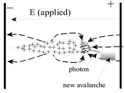
An electron from a primary ionization event needs to liberate more charge in order to create a detectable signal. One method to accomplish this amplification uses strong electric fields to accelerate the primary electron until it has sufficient energy to liberate more electrons from the chamber gas. In a traditional drift chamber, an electric field is established between two or more conducting wires. As an electron is accelerated towards a wire, it may obtain sufficient energy to ionize the chamber gas producing secondary freed electrons. The secondary electrons produced may themselves also be accelerated along the electric field lines and cause further ionization in a process commonly referred to as an avalanche.
The Gas Electron Multiplier (GEM)
The Gas Electron Multiplier (GEM), invented by Fabio Sauli <ref name="Sauli1997"/> in 1997, is a modern method using electric fields to create an avalanche condition. A GEM is a 50 micron thick kapton foil clad on both sides with 5 micron of copper. A staggered pattern of 50 micron diameter holes, equally spaced by distances comparable to the hole diameter, is etched into the copper clad foil. The small size facilitates the use of low voltages (300 Volts) to generate an electric field for amplification. By comparison, the typical drift chamber, operating on the same principle, would need more than 1 kV to establish a similar electric field.
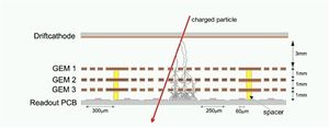
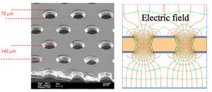
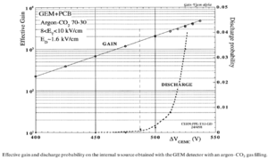
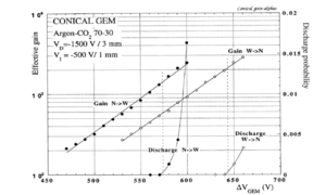
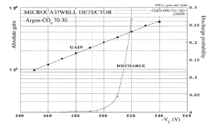
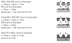
Some noteworthy advantages and disadvantages of the GEM are given below. The GEM foil is flexible enough to be curved, allowing cylindrically shaped ionization chambers with larger active areas. Unfortunately, the micrometer scale of a GEM foil makes it susceptible to damage from sparking at high amplification voltages. When the voltage increases from 525V to 600V (regardless of the card's pattern or the hole's geometry), the operating voltage range decreases to about 450 V or less as shown in Figure 3 <ref name="A.Bressan1999">A.Bressan, et al, NIM A 424 (1999) 321—342</ref >. GEM has a low noise signal because of the relatively low operating voltage, also the micrometer scale hole diameter increases the electric field flux through the holes, so a relatively high gain is obtained in the range of the operating voltage.
The Thick Gas Electron Multiplier (THGEM)
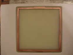
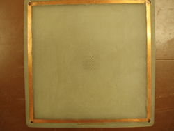
A Thick Gas Electron Multiplier (THGEM) is basically a GEM foil which has been scaled from micrometer to millimeter. A THGEM card is made from FR4/G10 clad on both sides with copper. The THGEM cards for this work are 12X12 cm square plates that are 1 mm thick and coated with 17 um thick copper cladding.2 Each card is chemically etched to leave a copper frame that surrounds an area of 100 cm2 as shown in Figure 4.A thin layer (around 5 micron) of ED-7100 resistive paste is applied (Figure 5) to allow potential �difference between the top and bottom layers and provide some spark protection by limiting the current flow along the surface. The card is machined to have 0.5mm diameter holes. The resistive paste near the holes is machined away to form a 0.2 mm thick rim around the hole. The holes are formed in a staggered array with a pitch of 0.8 mm.
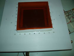
The THGEM cards are fixed in place to have the holes of each THGEM card aligned by the holders and separators in each corner. The cards are separated from each other by a vertical distance of approximately 2.6 mm. A drift voltage card, or cathode, made of copper paper is placed at the top of the cards at a distance of 2.6 - 4 mm from the closest THGEM card. The THGEM cards are placed inside a chamber made of two sheets of machined ertalyte (plastic), with a kapton window on the upper piece as shown in Figure 6.
The gas chamber is constructed using two 29.5X29.5X1.25 cm sheet of ertalyte plastic sheets that are bolted together by a number of M3 plastic screws located around the detector window to form a well closed cavity around the THGEM cards away from the surrounding atmosphere. The ionization gas, 90/10 percent Ar/CO2 mixture, flows in the cavity with a pressure of 1 atm.
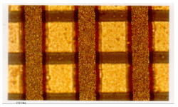
A read out plane exists on the bottom the detector. It consists of �different width cop- per strips that are organized to have the same pitch such that the upper strip width is 50 micron and lower strip is 150 micron; the two strips are separated by a 25 or 50 micron thick layer of kapton. Both of the strips are glued on a 100 micron FR4 plate to achieve reasonable flatness as shown in Figure 8. The read out plane is vertically separated by a distance of 0.5 mm from the closest THGEM card and it is connected to 16 connectors, each connector has 20 traces. The 16 connectors are sent to a 130 pin adapter allowing the use of a digitization card known as the VFAT card which sends a digital signal to a break board and then to the DAQ system.
THGEM preamplipfier is robust with a higher operating voltage and relatively higher gain with the least discharge. It has 0.2mm rim, 1 mm thick insulator and 2.6mm vertically separating distance from the next THGEM card, so the probability of discharge is minimized either in the card itself or with the other THGEM cards. But the detector may have a higher noise compared to that of the GEM preamplifier.
Detector Signal
Ionization
Ionization is the liberation of an electron from the confines of an atom. The minimum amount of energy required to liberate the electron is referred to as the ionization energy. Energy transferred to the electron in excess of this ionization energy will appear in the form of the ejected electron's kinetic energy. Photons or charged particles like fission fragments interacting with a gas volume can induce ionization. The ionization process depends stochastically on the ionization cross section which is mainly affected by the fission fragment energy, type of the fission fragment (heavy or light), the gas pressure in the chamber, and the atomic properties of the gas. Generally, the amount of energy needed to have an ionization event in a gas is the same on average <ref name="William"/>, regardless of the incident particle type or energy as shown in the following table for argon gas.
| Type of particle and its energy | 9 keV x-rays | 10 keV electrons | 40 keV electrons | x-rays Ar-37(K-capture)(5-25 keV) + beta | alpha 7.68 MeV | 340 MeV protons |
| Energy per ion-electron pair (eV) | 27.9 1.5 | 27.3 | 25.4 | 27.0 0.5 | 26.25 | 25.5 |
Gas Ionization by Fission Fragments
Fission fragments are also a source of ionization when they penetrate an Argon gas chamber. The energy used for such an event is highly dependent on the fission fragment mass and velocity. At low fragment velocities, recoiling becomes a competitive process that decreases the probability of ionization. In the case of a high velocity fragment, the probability of ionizing the gas increases to be closer to that of the alpha particles as they are penetrating the same medium.
The ionized nuclei that are ejected from a heavy nucleus that has undergone the fission process can ionize atoms in the vicinity of the fission event. The fission fragments have path lengths in matter which are on the order of microns. The energy loss process that these fission fragments undergo over the short range may be astochastically described in terms of three steps; as the fission fragment is totally ionized, fission fragment is exchanging the charge with the gas atoms, and as the fission fragment is totally neutralized.
First, the total energy of a fission fragment without a bound electron is given by:
where and v are the atomic number, the mass, and the velocity of the fission fragment directly after the fission reaction. The coulomb force represents the repulsion force between the ionized gas atoms and fission fragments, as well as the attraction force between the fission fragment and electrons. The second term dominates until the fission fragment begins to probe the charge within the neutral ionization gas atoms.
When the fission fragment decelerates, a charge exchange starts between the fission fragment and gas atoms, as the electrons are either scattering away from the fission fragment nucleus or attached to it as it is in motion. The total energy loss of the fission fragment suggested by Bohr in 1940 is given as :<ref name="Hyde">Earl K. Hyde,The Nuclear Properties of the Heavy Elements 3,Denver Publications, 1971, p 195-210 </ref>
where N is the number of particles of the stopping medium per cubic centimeter, and are masses of the fragment and the absorber, and are the atomic number of the fragment and the absorber, e is the electron charge, v is the fragment velocity, is the charge of the fragment, changes from 20 for the beginning of the track to a value of 2 close to the end of the track. is an impact parameter which tells at what distance the energy loss in the nuclear collisions is effectively zero owing to the screening of the charges of the nuclei by the atomic electrons, is the average oscillation frequency of the electrons in the atom.
This formula is an initial estimation of the total energy loss by the fission fragment under each stage of charge carrier exchange between the fission fragment and the gas atoms. It relies on how well Z-effective is estimated at each ionization step.
Consequently, the first term is dominant in the beginning of the interaction between the fission fragment and the ionization gas. The second term dominates close to the end of the fission fragment track.<ref name="Hyde"/>
Bethe's theory is commonly used to estimate the energy loss for fission fragments. It involves using a diverse model for the effective charge obtained based on energy loss data.<ref name="Rykov">V.A Rykov, atomic energy,vol83,No.1,1997 </ref>
where Z is the nuclear charge of the fission fragment, is the speed of the electron in first Bohr orbit, is the speed of the ion, are the nuclear charge and the atomic mass of the medium, is the mass of the electron, is the mean excitation energy of the atomic electrons of the medium of atomic number . A,B are the fitting parameters dependent on the medium, for example A=0.92, B= 0.72 for Light fission fragments. A=0.99, B= 0.82 for heavy fission fragments are they are passing Ar/CH4 (95/5 percent) medium.<ref name="Biwas">D. C. Biswasa, M. N. Raob and R. K. Choudhury,NIM,Volume 53, Issue 3, 1 March 1991, Pages 251-254 </ref>
The final step describes the neutrally charged fission fragment. The probability of ionization is very low during this step because of the fission fragment's neutral charge and low kinetic energy. The lowest energy at which a fission fragment can ionize a gas is expected to be equivalent to the energy of its weakest bound state electron which can be between 15.7 eV and 3.2 keV. In more specific studies that are based on classifying the fission fragments into light and heavy fission fragments, the researchers tried to measure the amount of fission fragment energy consumed by processes other than ionization. The energy is referred to as the ionization defect energy:<ref name="Valentine"/>
where E is the energy of the primary particle, I is the number of ionization events, and is the amount of energy use to produce an ion pair. Light fission fragments have a measured of 2.5 MeV when their initial energy was energy 67 MeV. <ref name="Valentine">J.M. valentine, C.Curran, Reports on progress in physics,21, 1 (1958) 1-29 </ref > and heavy fission fragments have measured of 4.2 MeV when their initial energy on average was 98 MeV. <ref name="Valentine">J.M. valentine, C.Curran, Reports on progress in physics,21, 1 (1958) 1-29 </ref >
The ionization defect energy experimentally indicates that you need lowest kinetic energy a fission fragment need to ionize the gas is actually higher than the fragments least bound electron binding energy.
The Neutron fission Cross Section for U-238 and Th-232
The cross section is defined by the following equation :<ref name="Ahmed"/>
where
Where is the number incident particle per uni area per unit time, dN is the average number of particles per unit time that interacted per unit solid angle, and is the solid angle. Since the cross section has an area unit (barn), some authors define this quantity as the area to which the particle is exposed to make an interaction. <ref name="Ahmed">Syed Ahmed, Physics and Engineering of Radiation Detection (Academic Press 2007) </ref> The cross section values are represented as a function of energy that gives the value of the cross section for each energy value and shows the resonance peaks. A theoretical description of the neutron fission cross section curve is not available, but statistically it is possible to evaluate the parameters for an assumption that describes part of the cross section curve within a certain error.<ref name="Hyde"/>
Neutron fission is one of the interactions that commonly takes place spontaneously or under certain experimental conditions. An incident neutron depositing sufficient energy in a nucleus to enable the nucleus to overcome the Coulomb barrier will cause the nucleus to split into fragment ligher nuclei (fragments) and particles. The new products interact with the surrounding medium depending on their energy and the type of the medium that contains them.
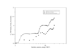
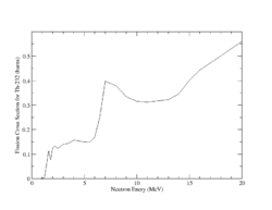
Both U-238 and Th-232 are members of the actinides group. They are characterized by relatively high neutron fission cross sections for fast neutrons with fission thresholds above the thermal neutron energy. The fission reaction in both elements is expected to eject 1-2 neutrons when the incident neutron energy is between 5-10 MeV as shown in Fig.9 and Fig.10.
 |
|
| Fig.9 U 238 fission cross section | Fig.10 Th 232 fission cross section <ref name="endf_Th_232_JEFF1.3">http://www.nndc.bnl.gov/exfor/servlet/E4sMakeE4 </ref> |
The Signal Size
An electron, freed by ionization and immersed in an external electric field, can ionize other atoms in a gas volume as a result of its acceleration in the external electric field. The number of additional freed electrons can be determined in terms of the external electric field (E), the pressure of the surrounding gas (P), and two fit parameters (A & B) which depend on the gas properties as shown in the equation <ref name="William"/>
The parameter is known as the Townsend coefficient. In the case of a THGEM preamplifier, an electric field (E) of is established when a potential difference of 2 kV is applied between the top and bottom sides of the plate that are 0.1 cm apart. In this work, the gas chamber contains a 1 Atm mixture that is 90% Argon and 10 % C02 by volume. The parameters from reference <ref name="Sharma"> A.Sharma,F. Sauli, first tawsend coefficients measurements for argon gas european organization for nuclear research (1993) </ref > are not given for this mixture. To estimate the THGEM pre-amplification, the A and B parameters for a 96/4 percent mixture gas mixture were used which are 5.04 and 90.82 respectively .
Using the above equation we would expect to be about per cm (which is a factor of 30 less than the coefficient for a GEM foil). A free electron traveling through the 0.1 cm THGEM hole should produce 12 additional freed electrons due to the Electric field of the THGEM pre-amplifier. We would expect a single freed electron to produce a maximum of electrons if it traverses three THGEM pre-amplifiers.
The number electrons emitted from a fission fragment is as result of a 30 MeV proton projected toward a U-238 target,<ref name=""> M. Facina "A gas catcher for the selective production of radioactive beams through laser ionization" mater thesis, Leuven 2004 </ref > while GEANT4 simulation of Cd-123 ionization gets the same result when it is traveling in 50 atm Ar/CO2 gas.(Cd-123 with 81.6 MeV is one of the fission fragment of a fission event for a 1 MeV neutron projected toward U-238). So the expected signal for the fission fragment detected by 50 ohm oscilloscope is roughly 2-20 mV at 50 ns.For a single ionization event, the THGEM detector signal would be small, while for a fission event the number of freed electrons will be substantially larger resulting in a large signal.
The Efficiency of THGEM
The efficiency of a detector is the ratio of the detected events to the total number of events entering the detector.
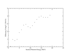
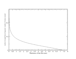
In order to detect a neutron entering the gas chamber the neutron must induce fission and the resulting fragments must ionize the gas. The cross-section for U-238(n,f) is given above in Fig.9. The probability of a fission event for a U-238 target varies from 1 to 5 % as shown in Fig.11.
The probability of a fission fragment escaping into the ionization gas is also required to calculate the detector's efficiency.
The number of fission fragments that escape from the surface of a UO3 film relative to the number of fission events is given by the following formula<ref name="Hudler">J.C.Hudler rdiation measurements 43,S334-S336, 2008 </ref>:
where is the number of fission fragments that escaped from the surface per unit area, A represents the number of fission interactions per unit volume, d is The thickness of film (um) and is The mean range of the fission fragments (12.07 um).
Assuming that the number of fission fragments is :
and the average range of the fission fragment through the emulsion is :
where <r> is the fission fragment's range in the thin film.
Summary
Thick gas electron multipliers (THGEM) will be used to pre-amplify a fission chamber used to detect the location of fast neutrons within the detector. The detector will be built using a U-238 or Th-232 fission target, depending on availability, to take advantage of the large neutron fission cross section between 0.1 - 1 barn. A fission event, in the above targets, stochastically ejects a fission fragment having an energy of 65 to 100 MeV that may lose energy in the form of ionization in a Ar/CO2 gaseous medium surrounding the fission interaction and free on average electrons. The electrons are directed by a drift electric field towards a THGEM preamplifier and, using three TGEMS, are amplified 10^6 to 10^7 times. The electrons are collected by a wire mesh read out producing a signal between 2 - 20 mV.
For Later
Manufacturing Environment and Detector Aging
Gaseous Detector manufacturing environment is always established to avoid any external effect that may interrupt the detector work. These effects come from the surrounding atmospheric environment of the detector like oxidization and dust accumulation. Also the effects appear in the working environment for the detector as it is surrounded with a noble gas like argon with contaminants under a high electric field effect; this produces chemical radicals attracted to the anode and causes non conducting anode. Finally, coating the THGEM cards by deposition used under a high electric field produces secondary electron emission from the coating, as a result reducing the life time of the of the THGEM cards.<ref name="Grupen">Particle Detectors, Claus Grupen & Boris Shwartz, 2nd edition, 2008 </ref>
Decrease the effect of the detector aging can relatively be controlled. Working in a clean room helps to avoid the contaminants carried by the surrounding atmosphere, and adding filters to the gas source decreases the contaminants carried by the gas.
Least fission fragment K.E needed for ionization
Ionization and Number of the the electrons produced
The sensitivity of THGEM as a neutron detector mainly depends on neutron energy range, material cross sections for ionization, neutrons rates of interactions, detector mass, background, noise (sparking and electronic devices used to collect the signal), materials surrounding the detectors and the strength of the electric field.<ref name="James"/> <ref name="William">William R. Leo,Techniques for nuclear and particle physics experiments,1st edition,Springer Verlag, 1995.</ref>
Radiation Backgound for Th-232 and U-238 Decay
The background energy spectrum for Th-232 has a main peak for alpha decay of energy 4082.8(14) keV combined with gamma rays of energy 63.81(1) keV and intensity 26.3(13) percent.<ref name="Th-232"> http://home.fnal.gov/~hannahnp/decay/decay.html, Jan.5 2011,http://atom.kaeri.re.kr/cgi-bin/nuclide?nuc=Th-232</ref >.
U-238 has also a close background spectrum as being mainly an alpha emitter, but decay alpha energy is 4274(5) keV with less gamma
intensity 1.02(15) percent when its energy is 113.5(1) keV.<ref name="U-238"> Fermilab,http://home.fnal.gov/~hannahnp/decay/decay.html, Jan.5 2011,http://home.fnal.gov/~hannahnp/decay/U238.html</ref >
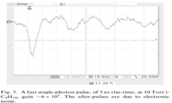
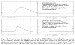
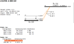 .<ref name="Th-232_d"> http://home.fnal.gov/~hannahnp/decay/decay.html, Jan.6 2011,http://atom.kaeri.re.kr/cgi-bin/decay?Th-232%20A </ref > |
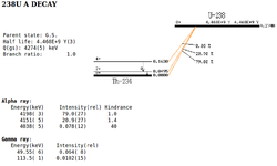 .<ref name="U-238_d"> http://home.fnal.gov/~hannahnp/decay/decay.html, Jan.6 2011,http:http://atom.kaeri.re.kr/cgi-bin/decay?U-238%20A </ref > |
The ionization from alpha particles and gamma rays is considered negligible compared to the one for any fission fragment,because of the enormous difference in mass, charge and kinetic energy. But when the fission fragments are absent, there will always be a signal representing the alpha decay.
File:Hadler on energy absorption effects in U Th thinfilms.pdf
Sensitivity of the THGEM as neutron detector for gamma radiation is minimized by properties mentioned previously about THGEM low amplification factor, also U-238 as a high cross section for gamma absorption in the desired energy range.
||
Neutrons are classified depending on their kinetic energy into three types: thermal, intermediate, and fast neutrons. The following table shows each type of neutrons and the energy range that they belong to.
| Type | Energy |
| Thermal | 0.025 eV |
| Intermediate | 1 keV – 500 keV |
| Fast | > 0.5 MeV |
<ref name="Dostal">General principles of neutron activation analysis, J. Dostal and C. Elson,p 28 Figure 2.3.</ref> <ref name="James">7-Ch. Jammes, P. Filliatre, B. Geslot, L. Oriol, F. Berhouet, J-F. Villard, “Research activities in fission chamber modeling in support of the nuclear energy industry”, ANIMMA International Conference, 7-10 June 2009, Marseille, France </ref>
THGEM detector is going to give a digital signal, coming from a defined localized point on the read out plate. This will give information about the sensitive area of the detector to the detected electrons which will be considered a reference for future detectors used for the same purpose.
References
<references/>
Paul Reuss ,Neutron physics,L'editeur EDP Sciences,2008.
