Difference between revisions of "HRRL Dec 13 2012Run"
Jump to navigation
Jump to search
| (One intermediate revision by the same user not shown) | |||
| Line 111: | Line 111: | ||
=Beam Spot out of 90 degree window= | =Beam Spot out of 90 degree window= | ||
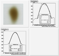
| − | The image below was taken by irradiating a glass slide placed against the 90 degree exit port for 10 minutes. The slide was scanned in and ROOT was used to plot the image. The image was inverted so the low intensity (dark) parts of the image would have larger amplitude pixels than the higher intensity (bright) parts of the image. | + | The image below was taken by irradiating a glass slide placed against the 90 degree exit port for 10 minutes. The slide was scanned in and ROOT was used to plot the image. The image was inverted so the low intensity (dark) parts of the image would have larger amplitude pixels than the higher intensity (bright) parts of the image. The beam position appears to have a gaussian like distribution with sigma of 2.6 mm in the horizontal plane and a sigma of 3.8 mm in the vertical plane. |
[[File:HRRL_12-12-2012_BeamSPotSizeUsingGlassPlate.png | 200 px]] | [[File:HRRL_12-12-2012_BeamSPotSizeUsingGlassPlate.png | 200 px]] | ||
| + | |||
| + | [[File:12-12-2012BeamSpotRootAnalysisCode.txt]] | ||
| + | |||
| + | |||
| + | [[12_10_2012_HRRL_DetectorTests]] | ||
Latest revision as of 04:55, 14 December 2012
Settings
Tune by Brian
Energy Scan
Jaws at 0.5 cm.
D1 (A) Image
Emittance Measurement
Beam Spot out of 90 degree window
The image below was taken by irradiating a glass slide placed against the 90 degree exit port for 10 minutes. The slide was scanned in and ROOT was used to plot the image. The image was inverted so the low intensity (dark) parts of the image would have larger amplitude pixels than the higher intensity (bright) parts of the image. The beam position appears to have a gaussian like distribution with sigma of 2.6 mm in the horizontal plane and a sigma of 3.8 mm in the vertical plane.


